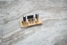
I today verified that pinkmouse's design still works")
Good, I need to build a couple more.
So, at the risk of asking a question that been asked tons of times and on an old thread to boot: what can I do with the Eagle files? Does the free version of Eagle allow you to import them and modify? Does it allow you make the Gerber files with it? Can you import Eagle into some of the other free PCB software?
If you are interested in the "ready to etch" pdf's I can upload those for you. It is a basic application of the LM4780 but it seems to work well. Pinkmouse, what is your exoerience with the zobel resistor and cap? I have not used it since I did not have the parts. If you can convince me to use them, I will purchase the parts
info
Hello from Serbia
I want to build this revision of chip amp. Special tnx to pinkmouse for nice revision of PCB. I want to build Stereo Amp so here I am
I mark all components to the sch file so if someone who build can tell me are this is ok?
One more question, why are PGND1, PGND2 separated from GND, SG1, SG2, CHGND, OG1 and OG2 ?
Thanks for all.
Hello from Serbia
I want to build this revision of chip amp. Special tnx to pinkmouse for nice revision of PCB. I want to build Stereo Amp so here I am
I mark all components to the sch file so if someone who build can tell me are this is ok?
An externally hosted image should be here but it was not working when we last tested it.
One more question, why are PGND1, PGND2 separated from GND, SG1, SG2, CHGND, OG1 and OG2 ?
Thanks for all.
Smallsized image
Sorry for small image in previus post:
http://www.dodaj.rs/f/1R/Eo/3HPHPbMo/1/sch.png
Sorry for small image in previus post:
http://www.dodaj.rs/f/1R/Eo/3HPHPbMo/1/sch.png
Hello
blueskynis tnx for fast replay
All this values of components I take from here:
http://www.unisonus.com/pl/p/file/c6f87e7d34faa18ced6d26ca51eefc12/LM4780_PCB_sch.pdf
I download data sheet, witch schematic i shoud watch...All schematic are difrent than pinkmouse version. I see that mute function is using like soft start the values are 8K2 and 15K resistors and 10uF. What else is wrong?
Hi tesla017,
you have some major errors in your posted schematic. Please look more carefully at LM4780 datasheet.
I don't think so, my circuit is an exact copy of the datasheet, (apart from component values that I explained on the first page) and works well. Can you explain further?
One more question, why are PGND1, PGND2 separated from GND, SG1, SG2, CHGND, OG1 and OG2 ?.
Hi Tesla. That's just a workaround to aid laying out a star ground, if you look at the pcb you can see what I mean. As for component values, they are all on the datasheet, the standard stereo layout. You may have to recalculate the soft start values for your voltage rails, but that data is given in the datasheet as well.
Oops, it looks like the datasheet has been revised since I did this layout. I'll try and find an old copy that I worked from, that should clarify matters.
edit: Right, I can't find an old copy of the datasheet, but as my work was based on that of Brian and Peter, you can use the schematic from the Audiosector website for component values.
edit: Right, I can't find an old copy of the datasheet, but as my work was based on that of Brian and Peter, you can use the schematic from the Audiosector website for component values.
blueskynis tnx for fast replay
All this values of components I take from here:
http://www.unisonus.com/pl/p/file/c6f87e7d34faa18ced6d26ca51eefc12/LM4780_PCB_sch.pdf
I download data sheet, witch schematic i shoud watch...All schematic are difrent than pinkmouse version. I see that mute function is using like soft start the values are 8K2 and 15K resistors and 10uF. What else is wrong?
Hi,
- Rz1 and Rz2 should be 2R7 ohms, not 22k
- R1 and R2 should be 22k, not 2R7 ohms.
@pinkmouse
I was commeting on his schematic not yours. Your schematic is in accordance with the datasheet.
- Status
- This old topic is closed. If you want to reopen this topic, contact a moderator using the "Report Post" button.
- Home
- Amplifiers
- Chip Amps
- Lm4780 SS PCB