A year and a half ago, I posted some impressions on testing various potentiometers: http://www.diyaudio.com/forums/showthread.php?s=&threadid=40676&perpage=20&pagenumber=1
I came to conclusion that PEC pot appeared to be most musical. In reality it wasn't the most practical choice: first of all the tracking accuracy on some units could be off by 6dB between channels (although the pot was specified as 10%). Also, some listeneres didn't like the "mushy" quality of the sound, so in the end I was still using Nobles in my Integrated amps.
However, I spent some further time experimenting with attenuators and it seems that switching attenuators are much better than pots.")
I came to conclusion that PEC pot appeared to be most musical. In reality it wasn't the most practical choice: first of all the tracking accuracy on some units could be off by 6dB between channels (although the pot was specified as 10%). Also, some listeneres didn't like the "mushy" quality of the sound, so in the end I was still using Nobles in my Integrated amps.
However, I spent some further time experimenting with attenuators and it seems that switching attenuators are much better than pots.
Attachments
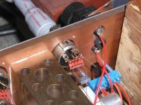
It seems like I've already found a perfect attenuator. It consists of a series, fixed resistor at amp's input and another, removeable resistor that sets the attenuation. In a picture, my current setup is presented. Please note that the socket is only temporary, it will be later replaced with much better grade, closer to amps' board.
All I need is a set of 6 resistors that I can plug in and depending on their values, I can adjust the attenuation in a 12dB range which is perfectly fine for most of my listening.
The quality of resistors is of great importance and in high resoulution system the differences can be easily observed. Specifically, for a GC amp, I'm choosing a nude Vishay in a series position and Caddock MK132 for shunt (Vishay does not work well here).
This setup is probably better than anything else presently available, although it's not particularly convenient
Attachments
Hi Peter,
Where did you get the grayhill? I have a 7gang one..but know someone who is looking for grayhill switches like that.
Regards,
Bas
ps..I have not tried that many attenuators..and especially not in the same setup. But so far I like the DACT units and my Grayhill with intactaudio AVC. Next up....DiyHiFiSupply amorphous TVC's. On the same Grayhill (7gang) so comparison should be easy.
Thanks!The one in a picture is 53M15-04-1-24S-F and you can probably order it from Grayhill directly.
It's really hard to say, but when you get 6db channel imbalance you definitely loose imaging.
The Nobels that I'm using are pretty good with regards to tracking accuracy and I found only one that was obviously out of specs. However, none of the pots I tried have the level of resolution a quality fixed resistor offers.
The Nobels that I'm using are pretty good with regards to tracking accuracy and I found only one that was obviously out of specs. However, none of the pots I tried have the level of resolution a quality fixed resistor offers.
It all started again, when I bought a used Placette RVC on the Audiogon. I've heard previously very positive comments on that attenuator, so finally I decided to give it a try.
Initially, inserted between NOS DAC and GC, I didn't really like it. It was a bit harsh, not liquid and kind of annoying. I still preferred the Levinson preamp as it was more laid back and tuneful.
Later, I completed the active buffer stage ( 6 ohm output imp.) and I plugged the buffer directly at the DAC output, and suddenly things changed. Placette became the best thing I ever had in my system, with a level of accuracy, resolution and openess I didn't expierienced before. it was not an issue of musicality anymore, things simply sounded right to the point that issues like tonality dynamics and musicality are not relevant any more.
I was kinda surprised.
Placette is based on a network of 14 resistors and 7 relays. It provides linear output voltage adjustement in 128 steps (if I'm not mistaken).
To see how good it is, I tried to "improve" on it with a circuit that consisted of a single series resistor inserted between two RCA jacks (input and output, series resistor being Vishay S102 or Caddock TF020) and the shunt element with DACT switch and nude Vishay across it. To my surprise, I couldn't improve on Placette with that circuit, contrary Placette was still better (in terms of resolution and opennes).
This leads me to conclusion that shunt element is equally important in a switching attenuator as the series counterpart.
Attachments
Finally, I can fully agree that in a properly configured system an active preamp isn't really needed, even with a GC. I recommend the following link for more details: http://www.high-endaudio.com/RC-Linestages.html
Here are some further comments with regards to Placette: http://www.goodsoundclub.com/Forums/ShowPost.aspx?postID=957#957
Here are some further comments with regards to Placette: http://www.goodsoundclub.com/Forums/ShowPost.aspx?postID=957#957
Peter,
Thanks for the updated information. Always good to hear about your new discoveries.
I'm enjoying the PEC in my preamp and integrated very much. I can surely see, though, how some folks might not like its particular sound.
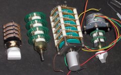
I have the Elma switch that's second from the left in your picture. I bought it through a group buy that was going on at Head-fi.org some time back. Shortly afterward, there was some talk of how the gold plated contacts on the Elma corroded over time leading to compromised sound. I don't know if that's the case, but there were a number of folks who wrote to concur.
Just out of curiosity, could tell us the names of the switches you have pictured? I'm also interested in which ones you found to perform particularly well.
Also, where can one purchase the nude Vishays?
Thanks,
KT
Thanks for the updated information. Always good to hear about your new discoveries.
I'm enjoying the PEC in my preamp and integrated very much. I can surely see, though, how some folks might not like its particular sound.
I have the Elma switch that's second from the left in your picture. I bought it through a group buy that was going on at Head-fi.org some time back. Shortly afterward, there was some talk of how the gold plated contacts on the Elma corroded over time leading to compromised sound. I don't know if that's the case, but there were a number of folks who wrote to concur.
Just out of curiosity, could tell us the names of the switches you have pictured? I'm also interested in which ones you found to perform particularly well.
Also, where can one purchase the nude Vishays?
Thanks,
KT
The biggest switch in a picture is Shallcross, which I think is the same as Shallco. It seems to have silver contacts.
Two other switches are from Elma. I like Elma for a reason of smooth switching action, I can't get used to hard turning of the others, Grayhill is particularly unpleasant.
I can't say how well Elma will perform over the time, but the preamps I sold two years ago still don't produce any switching noises (I'm using a better grade of Elma from Percy). Besides, a stepping motor can be attached to Elma for remote convenience. You can't do that with other, possibly better switches. Another advantage the Elma may have, is very little metal in contact area, and if low mass has some advantage in RCA connectors and binding posts, it may as well be important here.
Regarding nude Vishays, the info was posted here: http://www.diyaudio.com/forums/showthread.php?s=&threadid=73415
They are cheaper than S102, but also sightly different sounding. I'm not particularly fond of neither of them but couldn't find a better alternative yet. To me S102 is too soft sounding, the nude one is a bit too aggressive. I might try to aplly some silicone damping to nude verision to see if the sound can be adjusted in some way. For shunt application, Caddock is my first choice.
Thanks Peter,
Also, take a look at this assessment from the guy who used to do Counterpoint:
http://www.altavistaaudio.com/resistors.html
Best,
KT
Also, take a look at this assessment from the guy who used to do Counterpoint:
http://www.altavistaaudio.com/resistors.html
Best,
KT
Depending on a place in a circuit, there will be different preferences on resistors. So, in a NOS DAC I/V, nude Vishay didn't work well and was bettered by both Riken and Caddock (TF020), MK132 was rather bad.
In GC feedback and input shunt application MK132 was better than both TF020 and nude Vishay, Riken was behind those two.
In Levinson DACs, a nude Vishay is used for I/V.
In GC feedback and input shunt application MK132 was better than both TF020 and nude Vishay, Riken was behind those two.
In Levinson DACs, a nude Vishay is used for I/V.
Hi Peter,
Just a thought... why not a small board with all the resistors you need and a row of jumpers?
That way you could just change one jumper per channel for setting the volume.
Silver solder everywhere, more reliable than sockets, although the jumpers need to be decent.
There are lots of gold plated jumpers and connectors on old computer motherboards, you know?
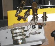
I hope nobody took too seriously my implementation of a "perfect" attenuator. Although it's really good, it can only serve as a reference for developing other circuits.
To be more practical, I intend to mount shunt resistors to a rotary switch and have at least 24 settings. The series element is fixed, the shunt is switchable, but a single resistor for each setting (altogether 25 resistors per channel, allowing 24 steps).
I'm also working on a more universal solution, where smaller number of resistors is used to create much more steps. It uses double sided PCB and relays (gold plated, silver clad contacts)
Attachments
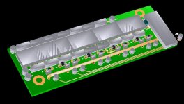
Yes. One board is needed per channel, balanced operation will require two such boards per channel.
The operation of the attenuator is very simple. There are two strings of resistors: one in a series position one in shunt. The resistors are shorted by relays in sequence and that produces 130 steps with average resolution 0.2 dB in most critical range section. There is never more than 7 active resistors (both series and shunt).
The signal path length is defined only by resistors size and relay switches length.
There will be display board available, remote control as well as encoder for manual adjustment.
Attachments
Attached is attenuator calculator. Any resistor values can be used, but it's better to multiply them by two in order to achieve smooth attenuation curve. The input impedance is fixed. There are two additonal resistors (user adjustable) to extend the atenuation range blow 42dB (in two 6dB steps down to 54dB or so).
Attachments
- Status
- This old topic is closed. If you want to reopen this topic, contact a moderator using the "Report Post" button.
- Home
- Amplifiers
- Chip Amps
- In search of a perfect attenuator