I think you should lower your power supply and you'll be fine. If it stays +/-30V, then you'll get more then 60W of dissipation on each chip, because in bridge configuration each chip sees half of loudspeaker impedance (in this case 3ohms). The chips will be very hot. I would provide them about +/-25V maximum to safely drive your speakers. According to LM3886 datasheet, with +/-25V you should get about 140W of undistorted output in bridge mode, and the chips wouldn't get hot.
If you use basic schematic from National's AN-1192 pdf, then you can easily connect everything p2p because this schematic doesn't have too many components.
I hope this helped a little.
If you use basic schematic from National's AN-1192 pdf, then you can easily connect everything p2p because this schematic doesn't have too many components.
I hope this helped a little.
costy_ro - Not much wrong with that schematic but I have a few questions about it:
Why take the trouble to match the resistors in the power stage ? Seems all they do is ensure the two halves have exactly the same gain but who cares if one side has 1% more gain than the other. Not like it would create a DC offset or distortion. Besides the resitors in the input stage are not matched so the two gains are not garanteed to be the same anyway.
Why have the 270 ohm resistors on the outputs of the input stage when we have resistors on the inputs to the 3886s ? I'd skip them.
There are too many capacitors. I would skip the caps on the input stage inputs and allow it to have a little DC offset which is then removed by the caps on th inputs to the 3886s.
As this is a pair of normal non-inverting amps on the output I would build them as per the carlosfm schematic Version 4 as seen here http://www.diyaudio.com/forums/showthread.php?s=&threadid=54697&perpage=10&pagenumber=16
I have build a couple of these and they are fine.
I always add an inductor wound as a few turns of wire around the ouput resistors Ro as per Rod Eliots chip amp seen here http://sound.westhost.com/project19.htm
Again keep the voltages down.
Sorry I get it now. That schema is only one side of of a bridge and has two chips in parallel hence the need for resistor matching. 4 chips total.
For 100 watts I would build two amps as per carlosfm schema (very similar to the ones shown) and drive them from the inverting stage. Surely two chips is enough and no matching problems.
For 100 watts I would build two amps as per carlosfm schema (very similar to the ones shown) and drive them from the inverting stage. Surely two chips is enough and no matching problems.
i was hoping to use only 2 radiators(1 for 2 chips) but i am wayting for answer from those who already made an amp like this,btw the power supply will be +/-25v@400VA.
if you want to make an amp(whatever the configuration) i suggest that u should make it after the app note sch. or after a sch that has been tested.
if you want to make an amp(whatever the configuration) i suggest that u should make it after the app note sch. or after a sch that has been tested.
costy_ro said:
I`ve got some questions:
1 do i need to el. isolate the chips from the radiator(i`ll put 2 bridged chips on one radiator)?
If you use LM3886T
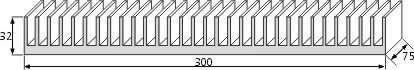
costy_ro said:2 is this a good radiator for 2 ic`s?
If its 32mm x300 x 75mm,then it is almost the size of the heatsink that national suggest for bridged parallel or 4 chips,you should have no problems with 2 ics
jaudio said:
If you use LM3886T
someone said that it is not necessary if i`ll power them from the same transformer
Ok maybe I misunderstood,I assume you mean electrically isolate. The lm3886T is non-isolated,so the part that is in contact with heatsink has the negetive rail voltage on it. If you dont isolated from the radiator(heatsink),then the radiator will also have the negative voltage on it.
I built a stereo amp with TDA7293 and mounted both chips on the same heatsink. The heatsink is isolated from the case. Chips are powered from the same supply and working with no problem for almost 2 years now.
In my designs I'm always trying to get thermal contact as good as possible, so in high power designs where power dissipation is important matter I rather isolate the heatsink from the amplifier case and mount chips directly on the heatsink then isolate chip from the heatsink.
In my designs I'm always trying to get thermal contact as good as possible, so in high power designs where power dissipation is important matter I rather isolate the heatsink from the amplifier case and mount chips directly on the heatsink then isolate chip from the heatsink.
Cro maniac said:. The heatsink is isolated from the case. Chips are powered from the same supply and working with no problem for almost 2 years now.
I was thinking from going that route but I know I will forget the heatsink is at the negetive supply and when I go to work on the amp


it seems i`ve got another problem;the radiator in the previous picture has a thermal resistance of 4,5 degrees and the Overture_Design_Guide13
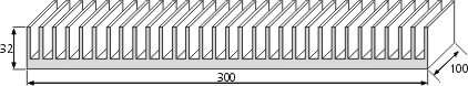
says it must be at about 3 degrees so i`ve found another radiator like this with th res 3,1dg(2,9 in the des guide) that seems more suitable.
Now,will this one be enough for all 4 chips(i`ll have 2 computer power supply vents cooling this radiator)
says it must be at about 3 degrees so i`ve found another radiator like this with th res 3,1dg(2,9 in the des guide) that seems more suitable.
Now,will this one be enough for all 4 chips(i`ll have 2 computer power supply vents cooling this radiator)
Attachments
Thermal problem
Hi
I tried uncessfully the LM3886 in bridged version.
For that, I used a stereo amplifier that I already built with two LM3886 Metalic case. ( this stereo amplifier works fine !)
My documentations is the National application BPA-200 and AN-1192
Now, in Bridge configuration, It works but only five minutes at the maximal power in a Resistive load.
After that, It's so hot that the LM3886 shutdown.
So, why can I use my amplifier stereo in full signal without problem, and when I bridge it, It doesn't work ??
Any idea ?
Is it a problem of current and in this case , Do I need to put 2 LM3886 in parallel ?
I have a nice output signal , means no distortion, no oscillations..
Thanks for your answer.
Remember you have to watch the power dissipation. What is the loads resistance? What is the supply voltage?
http://www.national.com/an/AN/AN-1192.pdf#page=1
page 3
If you need more current then paralleling will work.
http://www.national.com/an/AN/AN-1192.pdf#page=1
page 3
If you need more current then paralleling will work.


- Status
- This old topic is closed. If you want to reopen this topic, contact a moderator using the "Report Post" button.
- Home
- Amplifiers
- Chip Amps
- LM 3886 bridged