some noob questions as a follow up.
The PSU is part of the PCB, so it sounds like I can test everything without the LM3886 in place and make sure the voltages look good? Correct?
I have tested the transformer - pulled from a broken amp and it's only 2 primary and 3 secondary wires, hard to mess up (but I will still double check before powering on)
As far as bleeding the Caps - what kind/size Resistor do you suggest? Would a 5W sand cast or wire-wound be sufficient? and what "r", I have mostly lower values but could purchase some.
Thanks for the reply.
Additional question(s):
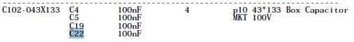
On the PCB - there is a designation for C22 (10n) - right next to the chip, but I can't find it in the BOM or schematics posted for the Rev C only the Rev A as part of the PSU.
Since it wasn't in the BOM I didn't order it, but need to know if it is necessary or optional? If optional do I leave it empty or use a jumper?
Thanks,
Do not use a jumper
I do not have a schematic to look at, but sounds like local decoupling cap. Maybe rail to rail. Leave out if an issue.
Do not short across. Big smoke will come from somewhere.
Additional question(s):
On the PCB - there is a designation for C22 (10n) - right next to the chip, but I can't find it in the BOM or schematics posted for the Rev C only the Rev A as part of the PSU.
Since it wasn't in the BOM I didn't order it, but need to know if it is necessary or optional? If optional do I leave it empty or use a jumper?
Thanks,
I do not have a schematic to look at, but sounds like local decoupling cap. Maybe rail to rail. Leave out if an issue.
Do not short across. Big smoke will come from somewhere.
Just build the boards as is but take time to double check each component for correct values and correct location. Inspect each joint after soldering for cold solder. You may want to clean the pads and component leads before starting. Enjoy the assembly process, take you time ")
PSU Cap Question
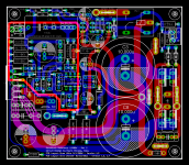
Here is a "snip" of the schematic and original BOM list, but only can find it in Ref A, not Ref C, weird. Thanks for the reply.
Thanks - and yes, I measured every component checked it on the BOM for accuracy and then on the silkscreen during placement. Always hard to take your time, when you've waited 7 months to build something everyone raves about...but I will resist the urge to get in a hurry (that's when the magic smoke most often occurs).
I do not have a schematic to look at, but sounds like local decoupling cap. Maybe rail to rail. Leave out if an issue.
Do not short across. Big smoke will come from somewhere.
Here is a "snip" of the schematic and original BOM list, but only can find it in Ref A, not Ref C, weird. Thanks for the reply.
Just build the boards as is but take time to double check each component for correct values and correct location. Inspect each joint after soldering for cold solder. You may want to clean the pads and component leads before starting. Enjoy the assembly process, take you time
Thanks - and yes, I measured every component checked it on the BOM for accuracy and then on the silkscreen during placement. Always hard to take your time, when you've waited 7 months to build something everyone raves about...but I will resist the urge to get in a hurry (that's when the magic smoke most often occurs).
Attachments
Additional question(s):
On the PCB - there is a designation for C22 (10n) - right next to the chip, but I can't find it in the BOM or schematics posted for the Rev C only the Rev A as part of the PSU.
Since it wasn't in the BOM I didn't order it, but need to know if it is necessary or optional? If optional do I leave it empty or use a jumper?
Thanks,
C22 is a bypass cap for C4 (rail to rail decoupling). Not needed if C4 is already hi quality. Most definitely DO NOT use a jumper!
Attachments
Last edited:
Do I have to have a heatsink on R3? It's a caddock 15W resistor and the BOM has a heatsink (which I ordered both styles listed), but I would need to trim either of them to fit and find M2 bolts/nuts to fit in the tiny rsistor hole (2.39mm, 0.094in).
Since it also specs for a 5W wirewound resistor, do I really need a heatsink since the Caddock is 15w rated? I will be using a 26Vac toriodal on 8 ohm speakers in a very large 3U case, but passive cooled (convection).
Caddock spec sheet shows at 100C is is derated by 40%, so 15w*40%=6w still higher than the 5W resistor required. Is that logical or wrong thinking?
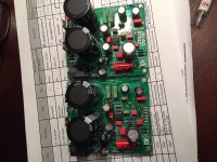
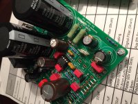
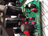
bullittstang, can u attach a pic of your board?
thanks
Here you go - only things missing is the Caddock resistor, C22 and the "chip".
Attachments
C22 is a bypass cap for C4 (rail to rail decoupling). Not needed if C4 is already hi quality. Most definitely DO NOT use a jumper!
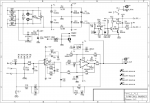
I took a closer look at the schematics and C22 appears across the AC inputs to the full wave bridge, while C4 is across the FWB DC outputs. The function of C22 is to snub ringing in the diodes in the FWB when they turn off.
There is an old article called "Diode Snubber Design" by Jim Hagerman. http://www.hagtech.com/PDF/snubber.pdf that better explains why you might want this cap in circuit than I can.
The author suggests that a simple ceramic disc capacitor can be effective in this spot as some lossiness is desired. If you have soft recovery or Schottkey diodes in that bridge you might not need the cap, but it's not going to harm anything either.
Regards,
Rob
I took a closer look at the schematics and C22 appears across the AC inputs to the full wave bridge, while C4 is across the FWB DC outputs. The function of C22 is to snub ringing in the diodes in the FWB when they turn off.
Rob
I think you are confusing C22 with C5. On the schematic I posted , C22 and C4 are clearly wired in parallel between V+ and V- of the LM3996 chip. They both run rail to rail on the DC input. This is also clearly confirmed by the PCB layout.
I assume the Ebay boards, used in this case, are consistent with Mauro's schematic.
Attachments
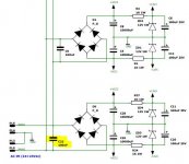
post4525 shows C22 wired across the two outer taps of the centre tapped transformer.
Post4526 shows C22 wired as the HF supply rail decoupling capacitor for the +ve rail.
Post4532 shows C22 next to R3 and is across the two supply rails
The sch in these three posts are not compatible.
Which C22 is Bullit asking about?
Post4526 shows C22 wired as the HF supply rail decoupling capacitor for the +ve rail.
Post4532 shows C22 next to R3 and is across the two supply rails
The sch in these three posts are not compatible.
Which C22 is Bullit asking about?
Last edited:
I responded to the schematic attached in post #4525 by user Bullittstang. On that diagram, C22 is a snubber for the diodes in the bridge.
Since Bullittstang did say that C22 is next to the LM3886, what you said about C4 and C22 are likely correct and the board layout and schematic you posted correlate.
Actually, in the photos of the boards posted by Bullittstang is does say rev3.
Regards,
Rob
Since Bullittstang did say that C22 is next to the LM3886, what you said about C4 and C22 are likely correct and the board layout and schematic you posted correlate.
Actually, in the photos of the boards posted by Bullittstang is does say rev3.
Regards,
Rob
Last edited:
I was asking why the schematics are different and I could only find the C22 referenced on teh Ref 1(A) version.
@Naaling - you posted the exact board I have, so what you mention appears accurate. I purchased them off the DIYA swap meet - was told they are from a group buy a few years back and are original.
I will leave C22 out and if I hear/see any issues, I can add it later.
Any thoughts on not putting a heatsink on R3?
Thanks for helping me on this - learning a ton with each project.
Last edited:
I will leave C22 out and if I hear/see any issues, I can add it later.
Any thoughts on not putting a heatsink on R3?
I believe C4 and C22 are wired in parallel. The capacitor should be as close to the LM3886 as you can place it. So I would not populate a 10nF capacitor but would move the 100nF capacitor from location C4 to location C22.
Amplifiers should be built to run at full power forever without burning up components. With that design criterion you will need a heatsink for R3. The group buy I participated in a few years ago included an Aavid 551002B00000G heatsink for R3. It did interfere with other nearby components and had to be trimmed so it would fit. That's ok since it had a bit more power handling capability than was needed so the loss in heatsink performance was acceptable. I can go through the math of the thermal design in another post if you want.
Thanks Andrew and Bill.
Andrew - yes you have good eyes not the exact design layout, but same circuit (I should have been more specific) I did take a pic of the board (front and back) and C4 and C22 are both across the V+ and V- supply tracks.
Bill - good to know, but the spec'd caddock has such a small hole, I'm having trouble finding a bolt. Thanks, I will keep looking.
- Home
- Amplifiers
- Chip Amps
- My "audiophile" LM3886 approach