I was just wondering if anyone has used linkwitz's design for the Lm3886 and power supply (www.linkwitzlab.com)?
He uses a standard 25A bridge rectifier in his power supply, so I was wondering why everyone seems to be going with discreet diodes. Linkwitz is a very highly regarded audiophile and EE (at least in my books) and I'm just surprised that more ppl haven't used his designs.
Alex
He uses a standard 25A bridge rectifier in his power supply, so I was wondering why everyone seems to be going with discreet diodes. Linkwitz is a very highly regarded audiophile and EE (at least in my books) and I'm just surprised that more ppl haven't used his designs.
Alex
2 Reasons....
1. BrainGT's kits come with discrete components.
2. A small discussion is seen here on the other why:
http://www.decdun.fsnet.co.uk/gaincloneFAQ.html
1. BrainGT's kits come with discrete components.
2. A small discussion is seen here on the other why:
http://www.decdun.fsnet.co.uk/gaincloneFAQ.html
Discrete rectifier bridge is a fashion here at the moment. I think that's simple reason and soon we will be using body diodes in mosfets as the next fashion!akunec said:He uses a standard 25A bridge rectifier in his power supply, so I was wondering why everyone seems to be going with discreet diodes.
 Don't forget that it looks a lot cooler with a discrete rectifier bridge. The coolness is an important factor and we should not neglect it and I mean it!
I built my PSU and the 3886 circuits exactly as Linkwitz says (except for separate transformers for L and R, since my amps sit inside the open baffle speaker).
Works like a charm, and I'm happy with the sound too.
Additional decoupling caps after the main caps were initially 10 uF and now 470 uF. I tried CarlosFM's "snubber" as well, it did seem to change the sound for more clarity back when I had 10 uF at chip ins only, but I haven't taken it off since I added the 470 uF caps. So I can't say if it is really necessary. Doesn't hurt though.
You'll notice that the PSU schematic already has those 0.1 uF caps on the AC secondary which were hotly discussed as a grand discovery, lately, here on the forums.
You'll also notice a smart cap network around the 3886 chips:
- a bypass cap for the feedback resistor to limit bandwidth
- a cap between -in and +in of the 3886, working with the feedback cap, to prevent back emf and HF from feeding through from the output to the diff inputs. None of the chip amps here have that AFAIK. As a consequence, he omits the output inductor as well.
- input RF filter
Also, note low resistor values (20 k feeback cap) for lower noise and lower HF pickup than many chip networks presented here.
My only mistake was to build 8 of those point-to-point as SL suggests. It was very tedious and I have some fears for long term reliability.
No problems with generic bridges, whatsoever. Used those on several occasions for chipamps. Being able to use excotic circuits and/or parts is part of the game for many DIY'ers though. Why shouldn't it be? Afterall, if one finds it worthwile and cool too; why not go ahead and do it? This is just one of the advantages of DIY. Oneself, and noone else, make the decisions
Steen.
BTW where on his page has Linkwitz hidden the LM3886?
Prob. just me gone blind
Steen.
BTW where on his page has Linkwitz hidden the LM3886?
Prob. just me gone blind
Talks about sound of rectifier's diodes ?
LOL. Someone even claimed he could hear the feet of his amp
I still cant find the 3886 on Linkwitz homepage

Can anyone give a pointer.
Steen.

Thanks a lot Rick. Looks good.
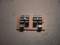
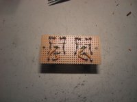
A bridge in the PSU is btw easier to have. I have made p2p bridges with discete diodes and that is ofcourse more time consuming. Have a look.
That is not entirely correct. The heated debate was about another cap, namely the one after the caps attached to a resistor.
AKA Zobelnetwork. You got the value right though
A bridge in the PSU is btw easier to have. I have made p2p bridges with discete diodes and that is ofcourse more time consuming. Have a look.
You'll notice that the PSU schematic already has those 0.1 uF caps on the AC secondary which were hotly discussed as a grand discovery, lately, here on the forums.
That is not entirely correct. The heated debate was about another cap, namely the one after the caps attached to a resistor.
AKA Zobelnetwork. You got the value right though
Attachments
steenoe said:
LOL. Someone even claimed he could hear the feet of his amp
Steen.
You can also fix those pesky knob resonances with genuine wooden knobs for only about $450. Available at some of the golden ear sites. Hurry, supplies limited.
You are right Tirebiter, the HiFi world is filled up with stuff like that.You can also fix those pesky knob resonances with genuine wooden knobs for only about $450. Available at some of the golden ear sites. Hurry, supplies limited.
The $450 could probably be spend om something more usefull
Like a new collection of CD's.
Steen.
That is not entirely correct. The heated debate was about another cap, namely the one after the caps attached to a resistor.
That was the main debate. In the same thread, the caps across the AC secondaries were "discovered" as well.
BTW I've also previously seen said Zobel (0.1 uF in series with power resistor of variable value) used across the AC *primaries* in published run-of-the-mill PSU schematics, labelled as 'transient suppressor' (I guess for neutralization of transformer inductance effects at turn-on and -off). Mains rated cap and resistor of course.
MBK said:- a bypass cap for the feedback resistor to limit bandwidth
I don't think that's necessary, and as these chips are not unity-gain stable, that can cause problems.
MBK said:- a cap between -in and +in of the 3886, working with the feedback cap, to prevent back emf and HF from feeding through from the output to the diff inputs. None of the chip amps here have that AFAIK. As a consequence, he omits the output inductor as well.
I use a 200pf styroflex cap across -In and +In on my main amp, with no detectable influence on the sound.
And this is on the datasheet.
Note: it's curious to see the discrete defenders to defend "integrated" rectifier bridges.
The reverse is also true.
- Status
- This old topic is closed. If you want to reopen this topic, contact a moderator using the "Report Post" button.
- Home
- Amplifiers
- Chip Amps
- Has anyone used linkwitz 3886 design?