Not very suitable for a gainclone:
this is an preamp, not a buffer!
This amp is working with some gain eg. voltage amplifier.
The input and output impedances are too high, for todays use.
And: there is a frequency dependent feedback in this circuit (including an electrolytic :-( notabene in the signal path). Maybe it is a phono preamp?
Franz
A buffer has unity gain or slightly less.Simple understanding, the buffer is unity gain or small gain.
I´m not sure what you mean but a preamp with 0dB gain is a buffer+0dB max. or +4dB max(such as mixer console).
and 4dB a rather low gain that is quite uncommon in preamps.
Maybe you are thinking about vu-meters and reference input line level signals?
joensd said:I´m not sure what you mean but a preamp with 0dB gain is a buffer
and 4dB a rather low gain that is quite uncommon in preamps.
Maybe you are thinking about vu-meters and reference input line level signals?
Yes,I mean that 0dB/4dB is the reference voltage level.Franz's explanation is more clear
")
rgds
digi
When you are looking for a tube buffer for a gainclone:
Did you miss this site up to now?
http://members.ozemail.com.au/~lisaras/index.htm
Regards
Franz
Did you miss this site up to now?
http://members.ozemail.com.au/~lisaras/index.htm
Regards
Franz
huangyong said:many Thanks folks, i still dont understand whether it's a pre or buffer? pls just tell me suitable or not, i am newbie in tube.
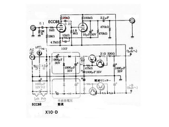
It's not suitable, as is. As others have said, it will have some voltage gain, so its technically an amplifier with the present feedback resistor values, not a buffer. But that's not the main problem. As Franz said, you have frequency dependent feedback (or gain, if you will). If I read the circuit correctly, the 10uf in parallel with 470k would give you increasing gain at very low frequencies (anyone care to speculate on the function of this part?), and the 100p in parallel with 15k would give decreasing gain above about 10k hz. It might work if you eliminate the two caps and the 470k resistor. The overall gain with the present feedback resistor might work ok, or you could play with the feedback resistor to get whatever gain you want.
I'm new to this stuff too, so I'd make sure someone can confirm this. Also, I'm not sure if you would have an imput impedence problem, as Franz suggested. Franz, care to elaborate a bit?
You could try to get this one to work, or you could try one that's already being used in this application, as Franz has suggested. Depends on how adventurous you want to be.
Sheldon
Franz G said:When you are looking for a tube buffer for a gainclone:
Did you miss this site up to now?
http://members.ozemail.com.au/~lisaras/index.htm
Regards
Franz
Hi Franz
Back in Oz again. Yep, http://members.ozemail.com.au/~lisaras/index.htm, that is still the original (but not best?) tube buffer for gainclone.
Regards
Joe R.
PS: The jet lag was a killer, then I got the flu and when getting over that, got bronchitis. Seems I paid for the sudden change in weather/temparature.
Sheldon said:
It's not suitable, as is. As others have said, it will have some voltage gain, so its technically an amplifier with the present feedback resistor values, not a buffer. But that's not the main problem. As Franz said, you have frequency dependent feedback (or gain, if you will). If I read the circuit correctly, the 10uf in parallel with 470k would give you increasing gain at very low frequencies (anyone care to speculate on the function of this part?), and the 100p in parallel with 15k would give decreasing gain above about 10k hz. It might work if you eliminate the two caps and the 470k resistor. The overall gain with the present feedback resistor might work ok, or you could play with the feedback resistor to get whatever gain you want.
I'm new to this stuff too, so I'd make sure someone can confirm this. Also, I'm not sure if you would have an imput impedence problem, as Franz suggested. Franz, care to elaborate a bit?
You could try to get this one to work, or you could try one that's already being used in this application, as Franz has suggested. Depends on how adventurous you want to be.
Sheldon
Oops, I goofed there. The second lp filter is actually around 30khz, so it's outside the audio band. Still don't know what the cap and 470k resistor is for, and and with the feedback resistor set for low gain, most of distortion produced by that bigger cap will show up in the output. So, as Franz said, you'd probably want to eliminate that. As far as input impedence being too high, I don't see why you couldn't use a lower value than the 1meg shown. Actually, other than that, the basic topology looks pretty interesting. People have reported good results with anode followers in pre-amp circuits. I'd like to find out more about it. With some changes, it might be pretty good, but I don't have enough experience to make specific recommendations.
Sheldon
Thanks jaudio,
I have built that buffer and it sounds good to me. but my concern is i am going to build monoblocks ;and utilizing only one channel of the tube in one block is not good. so i m looking for any buffer taht use 2 channel of the tube to maximize it's usage.
Thanks.
I have built that buffer and it sounds good to me. but my concern is i am going to build monoblocks ;and utilizing only one channel of the tube in one block is not good. so i m looking for any buffer taht use 2 channel of the tube to maximize it's usage.
Thanks.
Ive seen a schematic that used both halves in parallel but I must search for it,if I find it I will post it. Try seaching for a srpp buffer that will use both halves of the triode. Use the cathode follower side,to connect directly to your amp and use the top half for daisy chain
try www.platenspeler.com/homepage/uk_index.html
goto www.tubecad.com You will find a lot of information
try www.platenspeler.com/homepage/uk_index.html
goto www.tubecad.com You will find a lot of information
Originally posted by jaudio
goto www.tubecad.com You will find a lot of information
Thanx for that link Jaudio..
Very nice..- Status
- This old topic is closed. If you want to reopen this topic, contact a moderator using the "Report Post" button.
- Home
- Amplifiers
- Chip Amps
- Tube Buffer for gain clone.