Joe Rasmussen said:
Hi Franz
Back in Oz again. Yep, http://members.ozemail.com.au/~lisaras/index.htm, that is still the original (but not best?) tube buffer for gainclone.")
Regards
Joe R.
PS: The jet lag was a killer, then I got the flu and when getting over that, got bronchitis. Seems I paid for the sudden change in weather/temparature.
Joe,
All my VBGC were inspired by your buffer, it opened my mind to tubes.
I can't count how many I built, from the original, to regulated psu for the tube, and into premium parts too.
Get well soon.
JojoD
jaudio said:I might be missing something but how can you use 1 section of a tube in the first monoblock and the 2 section in the second monblock. If you have monoblocks that means you have two separate amps?
He's using 2 tubes: one half of the first in amp 1 and the other half of the second in amp 2. Switch them around and hey presto: good as new (except for the heater of course).
Take
tja said:
He's using 2 tubes: one half of the first in amp 1 and the other half of the second in amp 2. Switch them around and hey presto: good as new (except for the heater of course).
Take
jaudio,
that's exactly what I meant. Sorry for the confusion.
JojoD818 said:
Joe,
All my VBGC were inspired by your buffer, it opened my mind to tubes.
JojoD
Are you saying that you would not have built tube amps otherwise? If so, you have gladdened my heart. That was one of my primary aims, a tube project as safe as solid state because it did not use high tension (high voltage).
Now hundreds are building tube gear who probably were scared off (and perhaps rightly so) by potential lethal tube circuits and now doing what they thought impossible.
Joe R.
Joe Rasmussen said:
Are you saying that you would not have built tube amps otherwise? If so, you have gladdened my heart. That was one of my primary aims, a tube project as safe as solid state because it did not use high tension (high voltage).
Now hundreds are building tube gear who probably were scared off (and perhaps rightly so) by potential lethal tube circuits and now doing what they thought impossible.
Joe R.
That's exactly the idea, I wouldn't have touched any tube if I didn't stumbled on your VBIGC. I was already into discrete and chip amps when I first saw it. Now I built several tube preamps (with high HT too) and very soon (hopefully) an all tube power amp. Thanks to you Joe!
Oh btw, when I first saw your VBIGC I said... "I finally found a tube project that won't kill me, yahoo!"
What I learned from tube circuits is to have respect..... because the second you don't respect tube circuts, it kills you.

JojoD
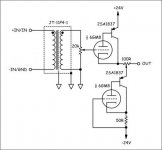
I have just completed a buffer based on Joes full buffer implemenation, which he hints at in his website. It uses a MosFet for the Constant voltage element, and one half of the tube as the CCS. I am running it at +/-85V, with valve rectification. I had real trouble getting hold of a suitable transformer, so in the end I used some speaker line transformers to step 6.3V up to the required 70V. I am also using an AC heater supply tied to the negative rail - no hum at all.
Sounds real nice, better than the +/-45V version I built before. A hell of a lot better than the basic Valve buffer Joe gave us (not that i'am complaining). I thank Joe for his original idea, and for the path of learning it has sent me on. I am now toying with the idea of a simple spud amp as my next project. The cost of decent tube power amp parts frightens me, so I might just stick to Preamps though.
Shoog
aditaquil said:Nuub question....
Can't sameone tell me the diff between tube and silicon?
Who is the best?
Simple. Whichever sounds best to you.
se
That the problem....I don't use tube on my diy project, it's to dificult to find and cost much money in my beloved country. If you can explain to me that the tube sound better, i'll try to build it up even make my saving zero.Simple. Whichever sounds best to you.

Not all valves are expensive. Of course, I have no idea of the availability of lesser-known (and hence cheaper) types in Indonesia.
If you want to hear the difference, you'll have to try it out, or maybe find someone who has a system based on valves. One thing SS can't do is the looks - there's nothing quite like a room lit by transmitter valves!
As you can probably see in my avatar, I'm not exactly impartial.
If you want to hear the difference, you'll have to try it out, or maybe find someone who has a system based on valves. One thing SS can't do is the looks - there's nothing quite like a room lit by transmitter valves!
As you can probably see in my avatar, I'm not exactly impartial.
Steve Eddy said:
Simple. Whichever sounds best to you.
se
Probably the best answer to that question I've ever seen! I have tube amps and sand amps and will build a tube buffered sand amp. There is a tube sound but is it better? Only you can answer that. (For me personally the answer is... sometimes.
)JojoD818 said:Shoog,
What does the statement on theschematic mean? "Proper cascode manor"?
And about the heater, being dc regualted, do you mean that the negative of the heater be tied to -85V?
thanks!
JojoD
I'll take a stab at this, trusting that Shoog will correct me if I'm wrong. The cascode arrangement is like running two separate triodes, on on top of the other. I think what he's referring to as "correct cascode manner" is that the correct heater polarity should be maintained between the two heaters. That is, the heater connection at the top triode should be connected the the positive end of the heater supply and the connection at the bottom heater connected to the negative side of the heater supply. The negative side of heater supply should not be referenced to ground, but should be referenced to the negative rail. In other words, use the negative rail as the ground for the heater supply.
Sheldon
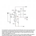
What I actually mean't was that on the data sheet it tells you when using the two halves of the valve in a stack, one half is specifically mean't to go on the bottom and one on the top. Only by using them in this manor can the correct heater to cathode voltages be maintained.
In the case of the ECC88 the bottom triode can have a potential difference of +/- 50V, the top triode can have a potential difference of +150V.
I am using AC heaters. I have just tied one leg of the heater supply to the negative rail. This keeps the heater to cathode potentials safe. If tied to earth, as I tried first, there seems to be considerable current flowing between the heater and the cathode, which manifests itself as loud hum. Do not be tempted to use DC heaters in order to eliminate this hum as the tube life is likely to be much shortened. If the heater to cathode potential is correct the AC heater will "not" introduce hum.
I hope that helps.
Shoog
Shoog said:What I actually mean't was that on the data sheet it tells you when using the two halves of the valve in a stack, one half is specifically mean't to go on the bottom and one on the top. Only by using them in this manor can the correct heater to cathode voltages be maintained.
In the case of the ECC88 the bottom triode can have a potential difference of +/- 50V, the top triode can have a potential difference of +150V.
I am using AC heaters. I have just tied one leg of the heater supply to the negative rail. This keeps the heater to cathode potentials safe. If tied to earth, as I tried first, there seems to be considerable current flowing between the heater and the cathode, which manifests itself as loud hum. Do not be tempted to use DC heaters in order to eliminate this hum as the tube life is likely to be much shortened. If the heater to cathode potential is correct the AC heater will "not" introduce hum.
I hope that helps.
Shoog
See, I told you he would straighten me out. Once again a little knowledge (too little, in my case) can be dangerous. Thanks Shoog. Good explanation.
Sheldon
- Status
- This old topic is closed. If you want to reopen this topic, contact a moderator using the "Report Post" button.
- Home
- Amplifiers
- Chip Amps
- Tube Buffer for gain clone.