Banned
Joined 2002
I'm not sure that's right. It's early surround sound technology, so be careful in your analysis. There is no provision for a center channel, and I'm not sure how the channels were powered.
There are outs for 4 main speakers, Left and Right A&B. There are two outs for rear speakers, Left and Right.
Dave
There are outs for 4 main speakers, Left and Right A&B. There are two outs for rear speakers, Left and Right.
Dave
kneadle said:Would you please elaborate after you finish celebrating?
Yea annoying him acting 10 yrs younger than he is... but he may be right, which creates the mystery of how the AC gets into the mains transformer (and what the purpose of the transformer on the main board is)....
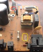
in the pic i have circled two connections... if the red one goes to the AC mains connection then Jason is right. The yellow one would be the 120VAC from the wall... where did it go?
dave
Banned
Joined 2002
JasonL said:the yellow goes to that little tranny sitting beside it as it is the soft turn on. the amp is on but not fully on. Meaning the power amp part is off but the rest may be on. this is how these recievers work..
J
That makes sense. When it was plugged in, it was in "Standby" mode if the amp wasn't powered up.
Will post more pics in a sec. I'm terribly intrigued by all this, and it started only as passing interest...
Dave
JasonL said:the yellow goes to that little tranny sitting beside it as it is the soft turn on.
No the yellow goes somewhere else -- it could well feed the mains transformer (it is after the on/off relay)... it can clearly be seen on the trace side of the board where the standby tranny gets its AC.
dave
Banned
Joined 2002
planet10 said:
No the yellow goes somewhere else -- it could well feed the mains transformer (it is after the on/off relay)... it can clearly be seen on the trace side of the board where the standby tranny gets its AC.
dave
that is what i ment. the yellow goes to the mains on the *BIGER* tranny : O )
First, the requested angle of the tf
An externally hosted image should be here but it was not working when we last tested it.
Now, when I first took it apart, I thought the heat sink was attached in some sort of heatsink "extended" way, never thinking that the chips were bent backwards....
So I figured out how to unscrew them from the heatsink and bent them up. There are SIX chips, 2 each of these (=4)
And these two:
Do you want to see the board they are mounted on?
Dave
An externally hosted image should be here but it was not working when we last tested it.
So I figured out how to unscrew them from the heatsink and bent them up. There are SIX chips, 2 each of these (=4)
An externally hosted image should be here but it was not working when we last tested it.
And these two:
An externally hosted image should be here but it was not working when we last tested it.
Do you want to see the board they are mounted on?
Dave
Transformer board writing
Missed that request till just now
Missed that request till just now
An externally hosted image should be here but it was not working when we last tested it.
An externally hosted image should be here but it was not working when we last tested it.
kneadle said:First, the requested angle of the tf
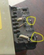
What i was trying to see was the other side of the pic below... but when i adjusted the gamma on the pic the two bright spots turned into pins... perchance do you have a cable that connects these pins to the yellow pins on the main board?
Attachments
I was hoping you wouldn't ask that one. I have two wires which I certainly disconnected from something--the only two wires in the whole blasted amplifier, but I can't for the life of me remember if they went from those two pins to the two pins we observed on the main board earlier. They're still shaped so that they do fit the pins without my manipulating them; so that's a really good guess, eh?planet10 said:
What i was trying to see was the other side of the pic below... but when i adjusted the gamma on the pic the two bright spots turned into pins... perchance do you have a cable that connects these pins to the yellow pins on the main board?
Those pins, by the way, have the op-amp "triangle" symbol near them, identical to the symbol on the tracing side of the Tx board.
The bridge is much smaller on the trafo board than the one on the main board.planet10 said:Is the bridge on the trafo board smaller (or the same) as the one on the main board? What voltage ratings are the 2 sets of caps on the main board?
dave
The voltage ratings are: 71 V and 8200 mF for the biggies, 42V 3300mF on the smaller set.
Dave
Banned
Joined 2002
yeah i think i'm beginning to think i'm right after all because A the whole amp does not run off one secondary. way to hi of a voltage for the amp. 2nd it costs to much to put in a regulated psu for the amp to run into a lower voltage.. so my best suggestion is to use a set of alligator clips with a inline fuse 2 amp. it is not going to blow a breaker or any thing just connect it. if i'm wrong it will blow if i'm right you can use your dmm to check the voltages..
connect it to...? Those pins you identified several pages ago?JasonL said:yjust connect it.
- Status
- This old topic is closed. If you want to reopen this topic, contact a moderator using the "Report Post" button.
- Home
- Amplifiers
- Chip Amps
- Salvaging Transformers