Banned
Joined 2002
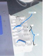
can you get me a better picture with light of the top of the tranny ?
ill mark out what goes where for you.. as i have done it lots..
My method..
1st Disconnect all caps from the tranny
2nd take a old lamp cord and keep the ac plug on one end.
3rd install a inline fuse of 1amp i used a fuse with a button top to add and remove replace the blown fuse.. at the other end where there is no plug add alligator clips. to it.
get me a better pic ill draw it on the tranny for you..
Jason
kneadle said:
Is that what a variac is for?
Thanks,
Dave
Thanks EXACTLY what a variac is for! apply the power slowly and monitor current draw!
For example, i was testing a new transformer, Big mama! there was nothing connected to the secondary side except my meter, BUT, one of the leads had accidentally touched another lead. I power up my variac, raised the voltage to about 2-3V and the current meter SPIKED! I know right away something was wrong! i powered down, checked everything, found the 2 shorted leads, seperated them and power up again, this time, no current draw and i could raise the voltage to full line potential and take my readings.
a variac is an essentail to in a DIY workshop. they can be purchased used cheaply! and there a great and fun first DIY project!
Variacs come in all sizes. I found a nice 1Kva unit for about $20.00 at a swap meet. I searched ebay and found a 0-150V meter and a 0-10 Amp current meter, slapped them into a project box with fuses for the primary and secondary sides and WallA! instant Home brew Variac! Total cost. $38.50
Zero

I suddenly understand very much. I need to go get me one of them thar variacs real quick. I'll post back on Monday.Zero Cool said:
Thanks EXACTLY what a variac is for! apply the power slowly and monitor current draw!
Zero
Seriously, understanding "variac" as a concept in the ideal realm has opened many doors very suddenly. This is good. I feel confident about active electronics today. Too bad I won't have a variac till Monday.
Thanks,
Dave
kneadle said:I am making progress, with a great step toward figuring it out with that tracing by dave (planet 10). First, I need to work up the courage to hook voltage up to this mama. Passive electronics is one thing, but adding amps and volts to a circuit proves me to be a newbie. Would someone like to suggest a safe way to get 120V to this naked Tx?
I have an AC cord with substantial alligator clips on them... (i also usually plug that into my variac, but before i got that i'd just plug it into a switched powerbar). You could also just solder the AC cable to the board -- what you don't want os the live AC connection moving on you...
Is that what a variac is for?
A variac plugs into the AC mains at one end and supplies a fused variable AC supply out the other... this is where the 12 VAC suggestion came from... connect the AC mains to the output of the variac, set it to zero, switch it on, and then while measuring turn it up until you have 12 VAC. Then measure the secondaries & multiply by 10... if something goes amiss, much less drama happens with 12v than 120V.
If connecting to 120V just be VERY careful, and make sure nothing is going to short anything or connections come loose etc.
Slow, methodical, careful.
dave
Zero Cool said:Variacs come in all sizes. I found a nice 1Kva unit for about $20.00 at a swap meet. I searched ebay and found a 0-150V meter and a 0-10 Amp current meter, slapped them into a project box with fuses for the primary and secondary sides and WallA! instant Home brew Variac!
My variacs are unmetered -- how did you hook it all together? I can probably dig relevant meters out, and with them in place the variac would be much more powerful.
dave
I like beer a lot, and I would hate to miss out on years of tasting beer while I sleep in a grave of my own digging.planet10 said:
Slow, methodical, careful.
I have the method, now; I'll go slow, and I'll be careful, especially with the above-mentioned motivation.
Dave
Banned
Joined 2002
planet10 said:
I have an AC cord with substantial alligator clips on them... (i also usually plug that into my variac, but before i got that i'd just plug it into a switched powerbar). You could also just solder the AC cable to the board -- what you don't want os the live AC connection moving on you...
A variac plugs into the AC mains at one end and supplies a fused variable AC supply out the other... this is where the 12 VAC suggestion came from... connect the AC mains to the output of the variac, set it to zero, switch it on, and then while measuring turn it up until you have 12 VAC. Then measure the secondaries & multiply by 10... if something goes amiss, much less drama happens with 12v than 120V.
If connecting to 120V just be VERY careful, and make sure nothing is going to short anything or connections come loose etc.
Slow, methodical, careful.
dave
what board.. there is no board. DONT solder any ac wires to the board with all the parts on it that is the secondary not the primary.
Get me a picture of the top of the tranny ill draw the ac in pin's for you..
Banned
Joined 2002
JasonL said:what board.. there is no board. DONT solder any ac wires to the board with all the parts on it that is the secondary not the primary.
Get me a picture of the top of the tranny ill draw the ac in pin's for you..
You can't read on the board where it says AC Mains? The other side has no-care connections, perhaps allowing the factory to swithc between 110 and 220V
dave
And I must add, I don't think anything was plugged into the Tx at those points. All wiring was indirectly routed to the Tx via that board.
It's entirely possible that I am remembering incorrectly, but I'm pretty sure that I was surprised enough by that to bring it to this forum.
Dave
It's entirely possible that I am remembering incorrectly, but I'm pretty sure that I was surprised enough by that to bring it to this forum.
Dave
kneadle said:And I must add, I don't think anything was plugged into the Tx at those points. All wiring was indirectly routed to the Tx via that board.
Jason was concerned enuff that my deductions were contrary to his that he called me...
Above answers Q1/ there was nothing connected to the other side....
Q2/ A double check... where did the ribbon attached to the AC Mains marked inputs come from -- the power switch?
Other points:
I have never ever seen AC Mains mean anything other than the wall. (Jason says those are heading to another -- a third rectifier in a cheap receiver?-- rectifier elsewhere)
And anytime i've seen these types of trafos, and the primary was on the other side, there is always a little vestigial circuit board connected to the trafo and wiring is connected to the circuit board.
This is where the variac does come in handy -- if Jason was right (which in the face of mounting evidence he is not) then the possibility exists that if you put 120V AC across what he thinks is a secondary you might exceed the insulation voltage rating (doubtful)
dave
Banned
Joined 2002
JasonL said:why would they put the main fuse on the opposite side ?
Inscrutable japanese...
and if it was the primary how does the AC get into the trafo with no wires connecting to that side?
dave
") Like I said, probably Monday.
Like I said, probably Monday.The power circuit
Here you go. This is the top (it broke while dissembling):
And here's the tracing (the input is top right)
Here you go. This is the top (it broke while dissembling):
An externally hosted image should be here but it was not working when we last tested it.
And here's the tracing (the input is top right)
An externally hosted image should be here but it was not working when we last tested it.
Banned
Joined 2002
Banned
Joined 2002
- Status
- This old topic is closed. If you want to reopen this topic, contact a moderator using the "Report Post" button.
- Home
- Amplifiers
- Chip Amps
- Salvaging Transformers