
Some of the advantages I can think of:
+ Easy soldering
+ Slim (potentially fairly flat) so it can be placed in small enclosures
+ Only a single resistor in the signal path
+ As many resistance values as you want (with the cost of bigger area, but you can put on on top or bottom, so it can be made pretty big).
It sorta reminds me of older pots/switches on 20's equipment.
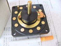
Jamh said:The switch in the picture is just for the connection mechanism inspiration.
By the way, who makes that switch in the photo?
se
Jamh said:Sorry I don't know the manufacturer. That's a rotary switch from the 30's. They were used in one-tube radios. the problem with these was that it was easy to accidententally touch the exposed brass.
From the 30s? Damn! It looks absolutely pristine!
Do you have just the one? I'd like to buy one or two if you have any to sell.
se
jam said:Going to hang a transformer on it......................
Does Sam Tellig like Musical Fidelity?
se
It looks like courser version of the TKD attenuator. Before the days of conductive plastic and linear attenuators these things (and there brethren) were found in every radio station . They were regarded for both high reliability and signal quality.
http://www.percyaudio.com/Catalog.pdf
http://www.percyaudio.com/Catalog.pdf
TKD Stepped Attenuator: The best off the shelf assembled attenuator that you can buy. Discrete resistive elements are used for each position in a series configuration
assuring very precise tracking between channels. Mounting is accomplished by three standoffs and screws on the front of the control so only a hole large enough for the
6mm shaft is required in your faceplate. Each stereo control requires a footprint 2.125" H x 1.75" W and 2.0" deep behind your front panel. The shaft extends one inch
beyond the back of the panel to which ithe control is mounted. 40 steps (1dB steps to -24dB, 1.5dB steps to -31.5dB, -33.5, -37.5, -39.5, -42, -45, -48.5, -53, -58, -65dB)
Specify 10K, 25K, 50K, 100K or 250K impedance.… $249.00/stereo attenuator $169.00/mono attenuator Our cost on these doubled 12/2002, so we will not restock after these are gone!
Nice concept!!!
Ive been thinking a bit about it, I see 2 problems in this construction that will have to be solved to make it really interesting.
First how to make the frontside (operator side) longer than the backside, in order to make it action reasonably smooth and easily adjusted.
Second, to work well, it must run SUPER smooth. That is fairly hard to achieve.
I have recently made a prototype for a 40 throw rotary switch.....it took a whole lot of fitting to make it run smooth....and some more fitting to make it run super smooth. Since you are forced to have the pivot point quite far from the actual switching action, you will need the switch to run even better than a good rotary switch.
What king of equipment do you have access to (machines and so forth)???
Magura
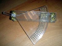
You know, as I'm building this, I'm thinking maybe the main area should be a PCB. It would make life so much easier.
My equipment is minimal. A radial saw to cut, and a bench press for drilling. An orbital sander to smooth things out.
The action is not too bad. I made the contacts springy, and those contacts are the only resistance to movement. But I agree that the knob should be made longer and perhaps stronger. Mabe I'll cut it and attach (screw) one made of aluminum or something.
The PCB idea is not bad, people could do resistors in series, or shorting, or whatever. A moving PCB!
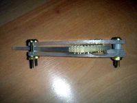
The PCB idea is good for a prototype, but quite bad for a final solution. The copper oxidates real quick. I have seen a few switches based on a PCB. The reason why they have passed my desk is that they were broken :-(
How about mounting a bunch of brass bolts in the board and use the heads as contacts??
Magura
How about mounting a bunch of brass bolts in the board and use the heads as contacts??
Magura
wow, great work, you really got me thinking.
One thing though. It may be easier to manipulate the contact plate and have the resistor system fixed. I know this is just a prototype, Im just thinking out loud.
Really cool, I never thought of building a custom manipulator before, I think Ill draw a little tonight and scan and post tomorrow.
Thanks,
Milo
PS. really cool...I know I said that already but I just can't believe that I haven't thought of doing this.
edit: redundant
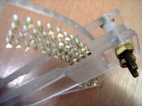
Wow.
That quite a bit of very patient drilling.
Have you taught about filing or sanding the heads of the tacks to make a flat uniform contact area?
It might be worth some time to fashion some sort of jig for cutting the tacks off, a sort of a mini miter box.
As you start to fashion the wiper, if your having trouble with uniform contact, a dual or bifurcated contact might be helpful.
Wonderful work!
- Status
- This old topic is closed. If you want to reopen this topic, contact a moderator using the "Report Post" button.
- Home
- Amplifiers
- Chip Amps
- volume stepped attenuator idea