I bought a Kenwood KA 405 several years ago as a reminder of my youngers years since this was the first stereo amp I bought for myself back in 1979. I hook it up, I noticed the right channel was very weak. I went head and Deoxit all my POTS thinking it would clean up any possible problems, but it didn't make a difference. So I figured I would go ahead and do a complete recap on it. I ordered a upgrade recap kit for it from High end audio online.
I also ordered the upgrades for the power supply caps. Though the orginals were 7500uf 50v I found out they dont make them anymore so went up to 8200uf 50v caps. I also figured while it was apart and after reading all the problems that other folks were having that I would change out the HA1457 IC on the preamp board with some HA1457 new replacements I found on EBAY! I also replaced the NJM4458D with the TI NE5532P on the controll board, and the 2SA1105 &2SC2580 TO-3P OPamps on the poweramp board with the 2SA1695 & 2SC4468 TO-3P Transistors. Figured I just upgrade everything or replace them since i was taking the amp apart.
While I was recapping I found a burnt out resistor on either R29 or R30 on the preamp board so just replaced both of them with a new resistor carbon film 100ohm 5% instead of the 10%. I removed out the relay switch on the power amp board and checked the relays as well as cleaned them they were not pitted or dirty at all in fact they look brand new shiney gold. After I had done all the work I went ahead and tripled checked my placement of Caps making sure I had not reversed polarity, and fired it up. The power came on but no click from relay. I shut it back down and realized the I had reversed the yellow, orange, red, and brown wires on the Preamp board, and the brown, red, orange, yellow, green, blue, and violet wires on the X11-1570-10(b/2) board volume pot.
Once I put the wires back into the right order. I went ahead and turned the amp back on and heard the speaker relay switch kick in. I left it on for a few minutes watching for any burning, smoking, overheat of components all seemed fine. I turned it back off decided to put a phono as input and wired up some speakers to it. Turned it back powers up but, no relay click no sound from either channels, tried a tuner as well .
Seems like it went from bad to worse looking for any Ideas, suggestions or thoughts as to what I might of done wrong?
So I'm wondering if maybe I had gotten some bad preamp IC fake HA1457 possibly and how would you be able to tell?
When I wired it up wrong could I have burnt out the Dual amp IC on the controll board? Also, should I have gotten Driver Transistors when I replaced out the OPAMP MOSFET TO-3P?
A little help as to which way to go would really be appreciated.
Oh little bit about me I actually went to school back in 1999-2001 to be a CET I completed the schooling but, actually never got my CET. I haven't done anything on electronics since I graduated from CET school. So please have a little patience and understanding here with as I'm having to try to refresh my memory on what the heck I'm doing!
Thanks so much for any help you could offer me! I
Thanks
It is a very pretty amplifier. I also keep a couple of those old amplifiers I couldn't afford as a boy. Pure nostalgic.
When you decide to refurbish old amplifiers you have two ways to go: Start the elaborate work of keeping the old electronics alive such that you only replace what is needed, or you replace (most of) the electronics with modern circuits and keep the beautiful casing.
If you go for keeping your old electronics, you need a circuit diagram when it does no longer function. The implementation structures of the old Japanese amplifiers were horrors, Bits of circuits everywhere and wires going in all directions. Without a diagram you hardly stand a chance.
In your case, if the relay doesn't switch on, it can be due to many faults in the amplifier, even in the pre-amplifier or in the relay controlling parts.
If you change (most of) the electronics, you have a modern configuration with modern performance. Many elder amplifiers lack transparency in their sound. You can design for a clear physical structure with a power amplifier part, a pre-amplifier part, a power supply part etc. You can leave out functionality you don't use. It will be more reliable but not "the way it was".
You have already done a lot to restore the old circuit. But, unless you can show us a diagram, only those of us having the diagram ourselves can help you further.
Good refurbishment.
Last edited:
Buying semiconductors from ebay can be problematic because, to put it frankly, there are many many fakes out there.
Unless the 2SA and 2SC devices were faulty (they are transistors, not opamps") ) then replacing them for newer devices could actually cause more problems because newer devices are made using slightly different processes and are generally faster (which could cause stability issues) and also have slightly different characteristics with regard to 'forward voltage' (which could mean adjustments such as bias are now out of range).
) then replacing them for newer devices could actually cause more problems because newer devices are made using slightly different processes and are generally faster (which could cause stability issues) and also have slightly different characteristics with regard to 'forward voltage' (which could mean adjustments such as bias are now out of range).
The HA1457 would be one of the last devices to suspect of 'natural failure' and certainly not something to just replace without at least having the rest of the amp functional.
When restoring something, always always look to fixing the original issue first before doing a blanket change of parts.
It is still probably an 'easy fix' but I suspect it may be well outside your comfort zone for diagnosing and troubleshooting.
Comprehensive voltage measurements are key, and the use of a current limited supply (DBT or dim bulb tester) are absolutely essential to prevent further damage.
Unless the 2SA and 2SC devices were faulty (they are transistors, not opamps
) then replacing them for newer devices could actually cause more problems because newer devices are made using slightly different processes and are generally faster (which could cause stability issues) and also have slightly different characteristics with regard to 'forward voltage' (which could mean adjustments such as bias are now out of range).The HA1457 would be one of the last devices to suspect of 'natural failure' and certainly not something to just replace without at least having the rest of the amp functional.
When restoring something, always always look to fixing the original issue first before doing a blanket change of parts.
It is still probably an 'easy fix' but I suspect it may be well outside your comfort zone for diagnosing and troubleshooting.
Comprehensive voltage measurements are key, and the use of a current limited supply (DBT or dim bulb tester) are absolutely essential to prevent further damage.
Thanks for your responses. FauxFrench here is where I got my service manual. Kenwood KA-405 - Manual - Stereo Integrated Amplifier - HiFi Engine I would post photos but need to figure how to post them from computor to this site.
Mooly I realize that the 2SC & 2SA are transistors my terminology may not be the best as I have said it has been almost 20 years since I have done anything with electronics. I do have quite a few diagnostics tools to utilize even though I am rusty in their use. I have a oscilliscope, 3 different type of Diode and transistor testors, 2 meters 1 True RMS and the other is a DMM, I have a frequency generator, I do not have a DBT(will have 1 in the next couple of hours) I also do not have a Variac Transformer ( will buy one of those on my next payday though).
Mooly I agree with you it maybe a little out of my comfort zone, but hey we have to get our feet wet sometimes. I spent over20k going to CET school only to never use any of it. I'd kind of like a little return on it, for my only use servicing my vintage electronics. I have quite the collection sitting collecting dust! I realize my skill set is a little on the weak side at the moment but hoping as I dive into this that it will trigger and bring back some of the knowledge I have lost, I am also hope to gleem as much info from all you kind folks as well!
So under your advisement Mooly should I pull out the 3 "NEW" HA1457 IC and put back in the orginals. Should I also pull out the NE5532P IC in the control board as well as the 2SC and 2SA I replaced and see if I at least have 1 channel of output as I had originally? As I stated before, I did find a burnt out resistor just past the HA1457 output side of the preamp board. It was a visble burnout I only found it when I was taking rough OHM readings of the resistors that I came up OL so I pulled it out of circuit and discovered it was burnt out on next to the board. I hope that you will continue to help me along and teach me to the best of both of our abilities as I know it is difficult to explain sometimes when you can't see what is going on!
Thank you so much!
If the amp is safe to power up then I would begin by checking the supply voltages to all the opamps you replaced. Lets see what that shows first.
The HA1457 should have plus 19 volts on pins 8 and minus 19 on pins 4.
The NE5532 should have plus 15 volts on pin 8 and minus 15 volts on pin 4.
Next check the DC voltage on the output pin of each opamp. All should be very close zero volts.
Those checks would be a good starting point that the opamps were operating correctly.
Okay Mooly I built my DBT, I will reassemble the amp to state that I can use Jumpers for connection in case I need to pull out a PCB to work on it! Once I get these voltages checked I will post a response with the information. Thanks for the link to how to upload photos. I will upload some as I change them down to JPEGs as I think the orginals are to large to post!
Thanks again very much!
Thanks again very much!
Mooly checked voltages out of preamp
1-IC had 13 volts out of 8
21 volts out of 4
0 volts out of 1
2-IC had 13 volts out of 8
21 volts out of 4
0 volts out of 1
3-IC had 46 volts out of 8
53 volts out of 4
0 volts out of 1
NE5532P dual amp
had 14.2 volts out of 8
14.2 volts out of 4
very small fluctuation of voltage from about 1- or less
Thanks again
Mooly FYI my relay switch is clicking on after about 5 seconds after I turn amp on! I also forgot to mention on the Preamp board I have 2 caps that I haven't replaced as the Upgrade kit had put the wrong value they gave me 22uf 50v caps, when it was suppose to be 2.2uf 50v so I am waiting for those to arrive. However if it is as fast as the original parts were to arrive I dont expect to see them until a month down the road. They are however in place I can Desolder them in out with very little problem!
Well you have something amiss with those readings.
I'm assuming the missing MINUS (and detail is everything when faultfinding) is just a typo.
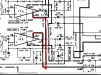
Look at the circuit diagram. Pin 8 of IC,1,2 and 3 are all fed from zener diode stabilizer D1. Pin 4 of all those IC's is fed from zener diode D2. These generate a stable PLUS 19 volt and MINUS 19 volt supply.
You should be seeing the PLUS 19 and MINUS 19 volts on those zeners. That same voltage should carry through to the above pins.
The 53 and 46 volts on IC 3 needs rechecking.
You need to be seeing -/+ 19 volts on pins 4 and 8 for all three.
I'm assuming the missing MINUS
(and detail is everything when faultfinding) is just a typo.Look at the circuit diagram. Pin 8 of IC,1,2 and 3 are all fed from zener diode stabilizer D1. Pin 4 of all those IC's is fed from zener diode D2. These generate a stable PLUS 19 volt and MINUS 19 volt supply.
You should be seeing the PLUS 19 and MINUS 19 volts on those zeners. That same voltage should carry through to the above pins.
The 53 and 46 volts on IC 3 needs rechecking.
You need to be seeing -/+ 19 volts on pins 4 and 8 for all three.
Mooly sorry about that, I rechecked IC1&2 or both reading at pin 8 +14 at pin 4 they're reading -19 with a fluctation up -20 on IC 1 , I dont know whats going on at IC-3 as its still reads +46 at pin 8 and -53.
I also noticed that R-27 and R-28 are extremely warm bordering to hot to touch. They're both a metal oxide film resistor 1 K ohm +/-5% 2w. I don't know if that has any bearing on the situation or not. You can feel the heat off these two resistors from the foil side of the PCB!!!
Thanks again
I also noticed that R-27 and R-28 are extremely warm bordering to hot to touch. They're both a metal oxide film resistor 1 K ohm +/-5% 2w. I don't know if that has any bearing on the situation or not. You can feel the heat off these two resistors from the foil side of the PCB!!!
Thanks again
The resistors running hot is normal, and one reason why metal oxides are specified.
Something very wrong with the readings on IC3. If you look at the circuit you will see those pins connect via R31 and R32 to the -/+19 volt rails.
I would begin by checking continuity from the pins themselves to those resistors, and then from there back to zeners. If you have damaged (open or floating) print then you can get weird non valid readings.
The only supply voltage available to that board is the -/+19 volts.
J1 and J3 will be around -/+43 volts. That is the unregulated raw supply before it reaches the zeners.
It is the reading on IC3 where you mentioned above that you still had 46 and -53 volts on it.
It is the reading on IC3 where you mentioned above that you still had 46 and -53 volts on it.
I dont know whats going on at IC-3 as its still reads +46 at pin 8 and -53.
Mooly Yes, I still have the +46v on pin 8 and -53v on pin 4. I traced it all the way back and did some other traces as well for continuity. I had continuity across 2 of my capacitors took them both out of circuit and they were not shorted. I have noticed on where J-19 is there is distinct cut of the foil. I'm not sure if that was factory cut as there is no green protective coating over that cut. That makes me question whether it was done after the fact by some other repair tech in an attempt to find the problem. My schematic is not an orginal it was downloaded Via HIFI website. So I see a dotted line across there so not sure to be honest with you. I thought maybe no ground would give a floating voltages, but they're constant no fluctuation like you would see with a floating ground. Has me scratching my head for sure! Anyways thats where I'm at right now!
Thanks
Thanks
Lets concentrate on pin 8.
Look at the diagram attached. Pin 8 of IC 2 and pin 8 of IC 1 both return to the same point (via the resistors of course) and that point is the stable 19 volt supply rail.
You say you have +46 on pin 8 of IC3. At some point along the way that 46 volts has to suddenly change to the correct 19 volts you are measuring for the other IC's.
Where is that happening ? Something has to be open circuit.
Do you actually have 46 volts on one end of R31 and only 19 volts on the other ?
If so then switch off and check the resistor out of circuit to see it measures correctly. If the resistor is open then its almost a certainty that there is an issue with IC3 and it has zapped the feed resistors. If that has happened then the negative rail feed will be the same.
Attachments
Tracing the voltage across from the J-1 & J-2 I had no varition a solid 42.5V +/- respectively, once they go across to D-1 & D-2 the voltage had jumped up to +48 and -55 the voltage drops only after it leaves R-29 and R-30 to IC 1 & IC-2. Shouldn't it of been rectified after the D-1 R-27 & D-2 R-28 or am I reading this schematic wrong? If that is the case then R-31 and R-32 should of rectified the voltage to the right voltage and then did not. However I pulled them out of circuit and they test correct on their Resistance!
Thanks
Thanks
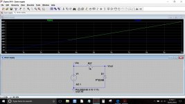
R27 and D1 form a classic zener diode shunt stabilizer. Raw (that means unregulated, noisy and variable) DC voltage is applied to R27. The diode connects via R27 to ground and clamps the voltage to 19 volts which will be the value of the zener.
The negative rail functions identically.
If you are seeing higher than 19 volt at either of the zener diodes then either the zener is faulty or you have inadvertently introduced a 'short' to somewhere else, or you have created a wiring error somewhere.
If you can measure higher than 19 volts across the either diode then that diode is open circuit/faulty.
This shows how it works. Vin is an unregulated supply rising in this case to 60 volts. The output voltage (Vout) is regulated to the zener diode voltage once sufficient input voltage is present.
Your unexpected high voltage readings must be coming from something else feeding into that board (a man made fault) or you are having problems making the measurements correctly.
All the rectification is done elsewhere in the power supply.
Attachments
Thanks Mooly, I know I am doing the reading correctly! I am just trying to figure out where I could of introduced a fault into the circuit board. Only placed that I have connected and disconnected the board would of been the 4 wire line in/line out from (X08-170-10)(B/4)PCB or the 3 wire +/-B voltage feeds. The only other modifications on this board that I have done are the recapping and replacements of the HA1457 IC. In the process of desoldering the line in and the line out I actually lost the input and output pads on the PCB. The ground pads didn't lift. So I scraped the off the protective coating to the trace and soldered in a piece of bus wire to connect my input and output too! I have checked that several times and the solders are good with no overflow to the ground off either wire. I checked and rechecked my Cap placement against the Schematic to ensure proper +/- placement. I guess that is why, so that leaves me scratching my head and hoping that somewhere doing what you have suggested I find the culprit of the enigma. I appreciate your willingness to help Mooly so thanks again. Think I'll pull both Diodes out and check them as well as both of the resistors. Any other thoughts or places that your experience says I should try? Thanks
- Status
- This old topic is closed. If you want to reopen this topic, contact a moderator using the "Report Post" button.
- Home
- Amplifiers
- Chip Amps
- Help on a Kenwood KA-405 integrated amp