An 18 or 19 volt zener of sufficient wattage would be ideal. 19 is an uncommon value. The voltage rating just sets the rail value to those IC's.
Wattage worse case is when no current is drawn from the rail such as when no opamps are fitted to the board.
43 volt input and an 18 volt zener means that 25 volts is to 'lost' across the series 1k resistor. Watts is V squared/R which is (25*25)/1000 giving 0.625 watts.
So you need a zener comfortably over that value.
http://uk.farnell.com/on-semiconductor/1n4746a/diode-zener-18v-do-41/dp/1467577
Before you go down the road of swapping parts I would recheck carefully all the voltages. In particular measure directly across each zener and see what the voltage is.
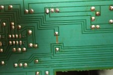
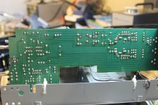
Mooly I am posting the Preamp board for you to look at! I have one spot that concerns me. Perhaps you can shed some light as to rather this is a factory open or some other tech's work on this amp and he cut it open. If so do I need a jumper?
Attachments
I owe you an Apology Mooly. I wasn't reading the voltage correctly, which I think you kind of figured out anyways. So lets get the voltage correctly and maybe than you can actually make sense of whats going here.
So after realizing when I read the B+/- voltages there was a 42.5 v on both sides I realized that I was moving the decimal point when I read all the other voltages.
So from B+ across R-27 I had 37.5v across the Anode to Cathode I had 4.8v(I had the same voltage reversing my probes) after R-30 I was at +1.3v
rechecking IC-1 at Pin 8 I had +1.3 v at Pin 4 I had -2.3v,
From B- across R-28 I had+37.5v from the Anode to Cathode I had 5.5v(with the same reading reversing my probes) after R-29 I was at -2.3v
Rechecking IC-2 found my values pin 8 +1.3v pin 4 -2.3v
Rechecking IC-3 had me at Pin 8 +4.5v and pin 4 -5.5v. Guess the devils in the details as you had said in your opening details. So hope this helps out in setting me straight with which way to procede now!
Thanks again and sorry for the mistake(guess that why its called learning)
No problem ")
The cut in the print could be factory work, possibly to correct a ground loop issue that showed up in use. Its quite common to see things like that.
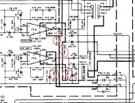
Voltages... you are measuring from ground for all these. That is J2 on that board.
If you can not measure +19 and -19 on the zeners then either the zeners are zapped or the IC's are pulling the voltage down.
Assuming you have not got the correct voltage then you can lift one end of R31 and R32 to isolate IC3. Does the voltage now come up on the zeners ?
If it does then IC3 is faulty.
If it doesn't then also isolate R29 and R30. That will remove the supply to IC1 and IC2.
If you now have voltage then one or both of those IC's is faulty. If no voltage then the zeners are faulty.
Look at the circuit... the method will make sense.
The cut in the print could be factory work, possibly to correct a ground loop issue that showed up in use. Its quite common to see things like that.
Voltages... you are measuring from ground for all these. That is J2 on that board.
If you can not measure +19 and -19 on the zeners then either the zeners are zapped or the IC's are pulling the voltage down.
Assuming you have not got the correct voltage then you can lift one end of R31 and R32 to isolate IC3. Does the voltage now come up on the zeners ?
If it does then IC3 is faulty.
If it doesn't then also isolate R29 and R30. That will remove the supply to IC1 and IC2.
If you now have voltage then one or both of those IC's is faulty. If no voltage then the zeners are faulty.
Look at the circuit... the method will make sense.
Attachments
Alright Mooly we made some progress today. So I pulled both R-31 and 32 out of circuit and the voltage increased across the zener by a couple of volts. I went ahead and pulled R-29 and 30 out of circuit and bang we had 20v across the zener. Guess my brand new HA1457 were fake(sigh) people are such damn crooks these days. Anyways I pulled out !C-1,2,&3 replaced them back with the originals IC's reconnected all my Resistors back into ciruit and we had the correct voltages all the way accross the board. Pin 8 is reading between +19.1 and pin 4 is reading -19.3v. Now which direction should I procede? Thanks again Mooly.
This amp appears to use a fixed bias scheme and that could make it dependent on the devices used.
You should check the DC voltage across the 0.47 ohm emitter resistors (R47 and R49 and R48 and R50. I would expect to see something around 15 to 30 millivolts give or take.
No speakers and no signal applied to test.
You should check the DC voltage across the 0.47 ohm emitter resistors (R47 and R49 and R48 and R50. I would expect to see something around 15 to 30 millivolts give or take.
No speakers and no signal applied to test.
Figures as I am posting the last comment I hear a click look over and see my VU meters bouncing around like they're getting input. I hear another click and the speaker relay switch clicks now I no longer the clicking of the relay switch after I power up the unit. I checked the preamp board everything is still reading that it is okay. I check the mv on the 4 reistors and now Vr 2 side I am getting 15mv on both R 48 and R 50. Check the other side vr-1 and R 47 and 49 are only reading 3mv. Sigh just when I was feeling positive bout this whole thing were back to where I was when we first started!!!
Thanks Mooly
Thanks Mooly
Those voltages are actually OK. With it being a fixed bias scheme it is impossible to tell the actual value that it will turn out at because it depends largely on the actual devices used.
Theoretically it should be nearer 50 millivolts but as its a domestic amp the manufacturers often play safe and under bias knowing that it helps long term reliability and saves cost and weight on more substantial heatsinks.
The reading will also vary greatly with temperature.
The relay clicking out sounds like a possible DC offset issue.
First question. Do both VU's bounce around the same when the fault occurs, or is it just one ?
When the fault occurs and the relay drops out can you measure the DC voltage at the junction of the 0.47 ohm resistors. Normally there should be well under 100mv here. This small voltage may be positive or negative. This time we are measuring from ground to the resistors and not across them.
When the relay drops out, has the voltage on those resistors in either channel increased ? If so then that indicates a DC offset issue in one of the channels power amps.
If not, and the relay is still 'out' then it may be a simple issue with the offset detect circuit. Possibilities here include a dry joint on R61 (a 3k3 which normally runs hot) and dries on the relay itself.
Another likely possibility could be a problem with the -/+15 volt supply to the tone control board.
Check for dries on R75 and R76 and the two zeners D15 and D16 (lower right of the circuit diagram)
Also check these supplies are correct when the fault occurs. Pin 4 and pin 8 of IC1 on the tone board should have -/+ 15 volts present.
The other day when the relay clicked off both VU meters were bouncing equally. When it happened I checked the IC on the control amp and It was 14.2 v +/- respectively on pin 8 and pin 4.
I will leave the amp on for awhile and see if it decides to shut down the relay switch as I am assuming that would be the only times I could actually check for some of the measurements you're telling me to check for. I will however check for cracks in the solder around those specific Diodes and resistors. I have actually taken quite abit of time to look over all the boards for that symptom. However, I've been wrong before so I will double check these locations that you have pointed out.
Thanks Mooly
I will leave the amp on for awhile and see if it decides to shut down the relay switch as I am assuming that would be the only times I could actually check for some of the measurements you're telling me to check for. I will however check for cracks in the solder around those specific Diodes and resistors. I have actually taken quite abit of time to look over all the boards for that symptom. However, I've been wrong before
so I will double check these locations that you have pointed out. Thanks Mooly
The VU meters respond purely to voltage changes at the power amp outputs. For both to do the same suggests a common cause and the power amps are really two independent circuits sharing only the main power supply.
Its more likely to be a problem before the power amps and that points to the tone board.
Bad joints can hard to spot. The last couple of pictures in post #1 here show the kind of thing to look for.
Sony CDP790 and KSS240 Restoration Project
Its more likely to be a problem before the power amps and that points to the tone board.
Bad joints can hard to spot. The last couple of pictures in post #1 here show the kind of thing to look for.
Sony CDP790 and KSS240 Restoration Project
Alright Mooly after firing up the amp, as it warms up the relay switch is clicking in and out of protection mode. I'll hear it click on and the VU meters start to dance than about 30seconds to a minute later the relay switch clicks and all is still about 3ish minutes later it cycles thru the clicking and unclicking with VU meters moving the right meter seems to dance a little more than the left meter. Wonder where the noise is coming from? thanks Mooly
Mooly the relay switch has quit clicking on now. I checked the voltages at R 48 50 at now reading 29mv or higher while R 47 and 49 are about .3mv or less. I looked over the control board didn't really see any places that looked like a dry joints but did a touch up across the board anyways. Whats your thoughts now
thanks
thanks
Sounds promising... sort of
Can we just be sure on the terminology here. The relay should normally be energised. If its not 'kicked in' then I would take that to mean it is not powered and closed.
If it is not powered and closed then there is still a problem with either the relay circuit/driver or something tripping the DC offset protection circuit.
With the switch in the 'Direct' position, does the amp work normally and play OK ?
- Status
- This old topic is closed. If you want to reopen this topic, contact a moderator using the "Report Post" button.
- Home
- Amplifiers
- Chip Amps
- Help on a Kenwood KA-405 integrated amp