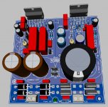
I have designed a dual-LM3886 amplifier PCB to use it for various purposes,
but mainly to drive an active speaker system in normal or bridged configuration.
My design is free, but ideas are welcome!!!
but mainly to drive an active speaker system in normal or bridged configuration.
My design is free, but ideas are welcome!!!
Attachments
Last edited:
If you intend spreading the word, then you need to include a schematic of what is actually on your PCB proposal.
We should not have to reverse engineer it to find out it is inadequate.
And many here are not capable of reverse engineering the PCB back to a sch. Everyone will have to take my word that this PCB is a complete waste of time, until you post some real information !
We should not have to reverse engineer it to find out it is inadequate.
And many here are not capable of reverse engineering the PCB back to a sch. Everyone will have to take my word that this PCB is a complete waste of time, until you post some real information !
I understand you. But I sad it is the basic datasheet schematic. fI somebody can not see on this very simple PCB what is going on, than should not choose electronics as a hobby...
If you expect everyone to download and install a program just because you fail to provide universally readable schematics to make discussion possible, you should neither post it in a forum nor expect many replies.
Can you post the diptrace schematic so that I can work with your design?
I have been using diptrace for a while now, Using your files will help me more too understand how the ground plane pours are created a little better.
Currently I have a Mini_Ref11 using a LM1876 almost finished except for the pours.
I will post my finished design in the thread were I got the design when it is finished.

Thanks !!")
jer
I have been using diptrace for a while now, Using your files will help me more too understand how the ground plane pours are created a little better.
Currently I have a Mini_Ref11 using a LM1876 almost finished except for the pours.
I will post my finished design in the thread were I got the design when it is finished.
Thanks !!
jer
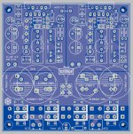
It doesn't look like you included the Thiele (L||R) network.
Tom
You are right, the LR network is the only one that is not presented on the board. That has the following reasons: 1. Nowadays my old LM3886 amplifiers do not have this filter neither and I am statisfied so. 2. The PCB size is limited to 100x100mm, so there is not enough free place to solder these components. 3. If you wish you can easy add it later (serial) for example at the LS terminals.
Can't see where GND(S1) and GND(S2) connect to GND(power).
Because of there is no connection yet...
I could not decide until now where to connect them. I must say, I am a little confused by the earthing concept of the "Neurochrome" design, so I left this question open up to now....
Can you post the diptrace schematic so that I can work with your design?
I have been using diptrace for a while now, Using your files will help me more too understand how the ground plane pours are created a little better.
Currently I have a Mini_Ref11 using a LM1876 almost finished except for the pours.
I will post my finished design in the thread were I got the design when it is finished.
Thanks !!
jer
It is good to hear if I can help for others...
Laying copper pours is not a difficult thing, you should playing a little around to experience the possibilities.
For example: right click on the pads and "Thermal Settings..." -> here can you set up how a pad should be connected to the pours.
Some people do not know really who is holding the rein: the horse or the rider.
I am not a charity institute! I am a hobbyst who made a topic for two types of people:
- who likes what I share and can use it in their own project
- and/or adds constructive comments to correct possibly errors
If you want a baked-out design than please leave this topic you too, and buy one in the nearest media markt. Thanks!
Zarandok, first off, let me tell you that I do understand your frustration, especially when submitting your labor for feedback the from community and end up receiving less than perfect reviews.
But if I may, I have been around here long enough to know that people like Andrew, Mark and JMFahey are some of the most knowledgeable people on here. Yes they do lack the sugarcoated writing style we would all love to hear, that's only because they would rather go straight to the point.
Just try to consider their input as constructive (albeit harsh-styled) criticism.
Oh and btw, a schematic is the first thing professionals look at because looking at the routing
- Status
- This old topic is closed. If you want to reopen this topic, contact a moderator using the "Report Post" button.
- Home
- Amplifiers
- Chip Amps
- Dual LM3886