Thanks hajj, these are understandable arguments...")
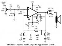
So I attached a shematic found in the internet. I have just the same but w/o LR network. Values may be different depending from a lot of things...
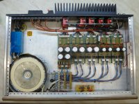
The PSU part is not a big deal: double graetz bridge with filter caps, then big puffer caps (2 x 2200-10.000uF).
So I attached a shematic found in the internet. I have just the same but w/o LR network. Values may be different depending from a lot of things...
The PSU part is not a big deal: double graetz bridge with filter caps, then big puffer caps (2 x 2200-10.000uF).
Attachments
Last edited:
L||R off board is not an issue. I have argued that off board is the better location for the L||R.
Cs must have both MF and HF decoupling located in the correct positions.
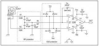
RF attenuation is missing from the input.
All the other components are OK. Only the value need refining. That can be done by any competant Builder.
See how easy it is after you post the sch !
Cs must have both MF and HF decoupling located in the correct positions.
RF attenuation is missing from the input.
All the other components are OK. Only the value need refining. That can be done by any competant Builder.
See how easy it is after you post the sch !
@AndrewT: That's exactly what I meant! 
@zarandok: Thanks for posting the schematics. Wasn't that hard, was it? It makes so extremely much easier to look at it and you notice things so much faster. No need to pressure people into downloading, installing a program and d-loading, unzipping and loading it into the application.
@zarandok: Thanks for posting the schematics. Wasn't that hard, was it? It makes so extremely much easier to look at it and you notice things so much faster. No need to pressure people into downloading, installing a program and d-loading, unzipping and loading it into the application.
Do you have experience about the size of the "MF decoupling" cap? The dataseheet is not exact, in there is written: 10 - 470uF on different pages. My actual one is working with 47uF, the PS cable bw. local decoupling and puffer is about 10cm.
Is there a really need for RF input attenuation?
Is there a really need for RF input attenuation?
Attachments
IC datasheet give lots of information.Do you have experience about the size of the "MF decoupling" cap? The dataseheet is not exact, in there is written: 10 - 470uF on different pages. My actual one is working with 47uF, the PS cable bw. local decoupling and puffer is about 10cm.
How many wireless transmitters have you got in your home?Is there a really need for RF input attenuation?
How many have your immediate neighbours got in their homes?
How many SMPS have you and your neighbours got in your homes and how many of them have effective filtering to reduce contamination of the airwaves? A mains powered LED lamp is an excellent example of virtually no filtering of an RF source.
NPO, or polypropylene.
F-3dB can be anywhere from 50kHz to 500kHz.
Are polystyrene styroflex types ok to use here?
The chassis is usually connected to the mains Protective Earth. This is mandatory for all ClassI equipment, from washing machines and heating boilers to audio equipment.
All exposed conductive parts should be connected to the protected chassis.
This includes all screw heads and other metal parts that project through the chassis to become exposed to touching.
The easiest way to meet this second requirement is to connect the Mains Audio Ground (MAG) to the Chassis at some convenient location.
In a Mono-block amplifier this causes no problem. Notice the symbol to the right of "ESD" in post 33. that is the Chassis to MAG safety connection.
In most multi-channel amplifiers this MAG to Chassis safety connection can introduce a loop around which interference current can circulate. This gives rise to avoidable interference noise.
Adding a Disconnecting Network into the wire connection from MAG to Chassis can attenuate the interference current sufficiently that the interference noise becomes inaudible.
This MAG to Chassis connection much be capable of passing Mains Fault Current and surviving long enough for the mains fuse to rupture and the arc to extinguish.
Last edited:
I don't know this "ground lift" concept, could you explain it a little? You mean the converter design (the schematic is from the datasheet)?
A ground lift separates the ground of the chassis from the input to eliminate hum loops. Especally with different input modes (balanced/unbalanced) it may be necessary or sometimes you can't get rid of hum noise or potential problems. That is important since you are planning to use it in different applications and you will most likely not have the needed means to improvise it when it is (unexpectedly) needed.
A ground lift can be realized in different ways, the best solution for most cases is a galvanic separation with an 1:1 audio transformer in the input.
- Status
- This old topic is closed. If you want to reopen this topic, contact a moderator using the "Report Post" button.
- Home
- Amplifiers
- Chip Amps
- Dual LM3886