Hello ive bought a tda1554 to try in my car as a replacement amp.
Some issues-
1) the pdf file doesnt mention heatsinking requirements.
so im going to just try any heatsink i can see in the store that looks substantial
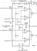
2)Im going to try the suggested schematic(very simple!)
which comprises of about 5 things.
-Question- will a 10k log pot do on the output?-as i dont see provision for volume,am presuming this will work fine.
Ive never used a chipamp but just need some basics
I presume that the 'substrate' ground means the back part of the chip,that i will heatsinking ,meaning the heatsink will be at ground potential,so i should be careful with my +12v....
its very simple questions really,but i simply dont know for sure and dont want to fry my ~9$ US chip
Cheers!
semiconductor data
Some issues-
1) the pdf file doesnt mention heatsinking requirements.
so im going to just try any heatsink i can see in the store that looks substantial
2)Im going to try the suggested schematic(very simple!)
which comprises of about 5 things.
-Question- will a 10k log pot do on the output?-as i dont see provision for volume,am presuming this will work fine.
Ive never used a chipamp but just need some basics
I presume that the 'substrate' ground means the back part of the chip,that i will heatsinking ,meaning the heatsink will be at ground potential,so i should be careful with my +12v....
its very simple questions really,but i simply dont know for sure and dont want to fry my ~9$ US chip
Cheers!
semiconductor data
Attachments
I also have a TDA1554, but I use it as a power amp at home. For the heatsink, I use an aluminum one 9cm wide, 6cm tall, and with 12 ribs projecting 1.2cm out the back. Overall, the aluminum is 3mm thick. You might want to use a larger one than that, since mine heats up very quickly. There are better amps out there. Mine sounds a bit washed out, but maybe it's just my room.
awwww nutz i made one of these amps a while back but it stopped workin all of a sudden, i suspect i blew the chip by plugging the power in the wrong way  ... anyway i need another chip but i dont understand german so i cant use that site is there an english one anyone knows about. Tnx
... anyway i need another chip but i dont understand german so i cant use that site is there an english one anyone knows about. Tnxhow do i check the chip if i already fryed it?
3 days ago i built the ampl using tda 1554 it made a loud and audible sound for a while but obviously it was putting out only half of the output signal. then it went silent and no matter what modifications i do the bird just won't sing anymore. How do i check if i already fryed my chip? it still gets hot and a small sound can be heard is it dead already? I'm new in electronics learned it only through the internet i would really appreciate it guys if someone could spare some time to help me thanks.
3 days ago i built the ampl using tda 1554 it made a loud and audible sound for a while but obviously it was putting out only half of the output signal. then it went silent and no matter what modifications i do the bird just won't sing anymore. How do i check if i already fryed my chip? it still gets hot and a small sound can be heard is it dead already? I'm new in electronics learned it only through the internet i would really appreciate it guys if someone could spare some time to help me thanks.
I am just wondering about the heat sinking of this chip, I have am planing on building one tomorrow but have not test it on full power yet (neighbors in the apartment block hate me enough already). I am currently using an CPU heat sink with its fan attached but I only super glued the chip onto the aluminum under some pressure, Is that fine?
Because the 2 screw's spacing I am having trouble with a normal heat sink.
It would only go on to an old ATX PSU's heat sink, is that enough thermal mass to keep the amp cool on max power?
Because the 2 screw's spacing I am having trouble with a normal heat sink.
It would only go on to an old ATX PSU's heat sink, is that enough thermal mass to keep the amp cool on max power?

Don't. Their minimum order for international shipping is 150 €.
it still gets hot and a small sound can be heard is it dead already?
A very common mistake with that IC is, although it is specified for supply voltages from 6 V upwards, the mute pin (14) needs more than 8,5 V to make the amplifier work.
I am just wondering about the heat sinking of this chip, I have am planing on building one tomorrow but have not test it on full power yet (neighbors in the apartment block hate me enough already). I am currently using an CPU heat sink with its fan attached but I only super glued the chip onto the aluminum under some pressure, Is that fine?
Probably, because these ICs are used in car radios, where they often only have the case without any air circulation around as heatsink. If they are lucky, they get a very small aluminium strip on top of that. However there is information about heatsinking in the datasheet. Looks like 60 W dissipation up to 62,5 °C. The dissipation formula is U/2*PI²*R gives ~0,9 W for all four output stages feeding 4 Ohm from 18 V, ~1,8 W, when all four stages feed 2 Ohm. Add the IC's own consumption of 0,16 A x 18 V worst case, which is another 2,9 W, you get 3,8 W or 4,7 W. A much smaller heatsink can deal with that amount of power. You should use thermal compound instead of super glue, and you can certainly skip the fan.
My observations & experiences
TDA1554Q best robust car amp can be listen in home environment. It's simple to build require few components but good power supply. And very stable chip.
I am listing 4 amp = 8 channel from last 10 months approx which is mounted on 4"x10" heatsink and not using any cooling fan. 12-0 5 amp Single transfomer & bridge power supply having 4 nos 4700uf 25V caps. Increasing volume = increaseing heat. Yes, it is depend on your listening test.
Probably, because these ICs are used in car radios, where they often only have the case without any air circulation around as heatsink. If they are lucky, they get a very small aluminium strip on top of that. However there is information about heatsinking in the datasheet. Looks like 60 W dissipation up to 62,5 °C. The dissipation formula is U/2*PI²*R gives ~0,9 W for all four output stages feeding 4 Ohm from 18 V, ~1,8 W, when all four stages feed 2 Ohm. Add the IC's own consumption of 0,16 A x 18 V worst case, which is another 2,9 W, you get 3,8 W or 4,7 W. A much smaller heatsink can deal with that amount of power. You should use thermal compound instead of super glue, and you can certainly skip the fan.
oh, so the heat sink on the right of the pic will do? some web site also mentioned about the chip dissipating 25W of heat on full volume. but anyways how did you obtain the formula U/2*PI²*R, whats U?
Oops, just noticed that I skipped a square. The correct formula is Pd = U² / (2 x PI² x R). The power dissipation is then 16,4 W with 4 Ohm on all channels plus the IC's 2,9 W consuption, hence 19,3 W. So you rather use the left heatsink, if you want to push that amplifier every now and then.
U is voltage. You can find that formula in technical literature.
U is voltage. You can find that formula in technical literature.
Yes, P is power. Your formulas are correct. For the dissipation you want to know the power that heats the amplifier, which is the average power. The average value for a sine wave is its peak value times 2 / PI for I and for U.
I am not sure about the thermal resistance of super glue. There are thermal glues, which are a combination of glue and thermal compound.
I am not sure about the thermal resistance of super glue. There are thermal glues, which are a combination of glue and thermal compound.
I finished building this amp. however the result is not very good. this chip was only drawing like 0.6 A driving a 8ohm load at 12V, it also need a input voltage swing of like +-5V to produce any reasonable amount of output. I am thinking of making another amplifier out of a LM1875 or something and use 2 battery for it.
The TDA1554Q has a fixed gain of 20 dB or 10x. A 5 V input signal would be a theoretical 50 V output signal, if the rails would not limit that. Check, if you have 8,5 V or more at pin 14. With less the amplifier is muted and you only get 2 mV of output for 1 V of input. 5 V would then be 0,0000125 W into an 8 Ohm load or ~50 db less than you get from 1 W.
- Status
- This old topic is closed. If you want to reopen this topic, contact a moderator using the "Report Post" button.
- Home
- Amplifiers
- Chip Amps
- tda1554 amp attempt...