You don't like my implementation using exclusively 1uF caps and 1k resistors??? I got a great deal on a few thousand of these so, you know, might as well put them to use...
As kevinkr noticed, I have drawn the schematic but not (yet) assigned any meaningful values to the components. I'm working out the topology at this point. Keep in mind that it's not possible to provide all the correct values without knowing the exact driver, enclosure, and alignment that one is using, so most of these will remain placeholders until a specific example is given.
Sorry to much Chardonnay last night

Cheers ,
Rens
Nearly missed this, as it's in Chips ! I've been interested in AB ever since it was first reviewed, back in the day ! Always wanted to hear one, but never did, & hoped one day to build one. Well after All these years, i might just get to do both. I wouldn' use ChipAmps myself, rather use the non inverting output to feed a regular Amp. Looking forward to further developments etc in here. All the best with it.
Experimentation, 37vdc rails, and a few samples. You can get somewhat more than the 45 linear watts, depending on successful (ofttimes creative) decoupling.That's not what the datasheet says... see for instance Figure 10. What's your basis for this power spec claim? I can see that this may be true but only in the case of rail voltages that are around +/-30V or so. That's much less than what the ICs can work from.
So, actually, I'm not sure if the 45 Linear Watts estimate is correct; however, I'm absolutely sure you Can go that far (per each chip) without any bass-reducing influence from the on-chip limiter.
With 8 chips, that's at least 360 watts plus considerably larger peaks available for dynamic bass impact.
I believe that the datasheet's headline power figure is how much it takes to break it, just like discrete device headline power figures. Also ST's datasheet has figures in watts RMS, but my quote is linear watts (watts RP, real power), which has a somewhat different meaning. How much you can advertise versus how much is usable (for giant bottom-octave bass waves), can be much different.
The deal is that if you want trouser flapping power, then you'll probably need enough outputs for the job. That is equally true of both discrete and chips.
Although little chip amplifiers barely get by on peak dynamic power; however, when scaled up to biggie size, the many-chips composite amplifiers release huge dynamic shockwaves (if well rigged, of course). So, when scaled up, there's no lack of power. Typically, mine do a huge breeze of audio.
40x is suggested for start-up.Thanks for the above comments on the design details, especially the suggested gain although that seems a bit high.
With a great deal of cleverness and some hacks, it should be possible to get it down to 36X still stable even when pushed all the way to the rails, but such fine tuning can be laborious.
The middle ground, 38x is not very difficult.
Layout and successful/creative power decoupling and power supply voltage, will all affect the ideal gain setting, so that's pretty much a thing to fine tune after you've built it. True of most chip amplifiers, allowing the gain setting that IT wants provides the stability that you want. Gain is the main stability control of a chip amplifier, so choosing an arbitrary figure won't be useful; however, a nice multi-turn cermet trimmer for feedback-shunt-leg resistor could be very useful.
These chips give maximum performance when set exactly--even more precisely than fixed resistor values can do.
If the gain is too small, the amp will put more power into the heatsink and put less power into the speaker. Setting the gain a bit high avoids that problem.
It will not be necessary for extra power consumption for conditional stability to accommodate treble imaging needs in a subwoofer amplifier; therefore, lowest possible gain is not the most useful target. Instead, "generous stability" is what a subwoofer amplifier needs, so it can run especially cool, have huge dynamic punch and have good durability.
This is also true of TDA7293's when used full bandwidth and that's where the gain thing is inconvenient for treble imaging needs.
Last edited:
Nearly missed this, as it's in Chips ! I've been interested in AB ever since it was first reviewed, back in the day ! Always wanted to hear one, but never did, & hoped one day to build one. Well after All these years, i might just get to do both. I wouldn' use ChipAmps myself, rather use the non inverting output to feed a regular Amp. Looking forward to further developments etc in here. All the best with it.
This is sort of a multi-disciplinary project combining an amp and EQ/boost/MFB (can I say that?) network and it could have been started here or there within these forums. Part of the original idea was to clear out my stock of TDA7293s so it ended up here. If the project is wildly successful I could work on a version that uses a class-D amp, but that is far in the future for now.
I would prefer a holistic design approach, but I am also considering separate boards for the line level circuit and for the amplifier so that these could be split from each other more easily in the future. Baldin took that approach in his design a few years back. I have always been wary about doing it that way, feeling that this opens up the possibility of (for instance) accidentally choosing a power amp that is inverting when expecting a non-inverting amp, connecting the speaker and then watching the system self-destruct at power up. Designing the system (amp+circuit) as a whole gives me some peace of mind in this regard.
A few more topology tweaks and now things are finally coming in to focus!
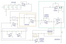
I added an input network and buffer - this is directly lifted from Bob Cordell's "Super Gainclone" circuit. The DC servo and power amp input buffer idea is also borrowed from that design. I've re-arranged the MFB and DC-servo (no longer 2-pole) so that I could add the power amp input buffer, which will allow me to keep the input impedance to the power amp IC low. Now the MFB op-amp can't be eliminated, so if that filter is not needed or desired it should be converted to an inverting buffer. This can easily be accommodated on the PCB.
To cut down on the confusion I have put component values into the circuit where I know what they will be. For the parts of the circuit that depend on the driver and box parameters that are required for a particular ACE-BASS or LEMF application those component values have been removed since they were meaningless anyway.
Feel free to comment on what is shown. At this point I could use the input. Also, thoughts on the op-amp types are welcome - I am considering using OPA2604 (inspired by Bob Cordell again) because of their FET inputs, low distortion, and ability to drive low impedance loads. A cheaper option might be the TL072.
Latest circuit effort attached.
Attachments
Of some relevance, could be this, from: Lenard Audio
(solid state amplifier has been fitted with current drive adapter)
(solid state amplifier has been fitted with current drive adapter)
Last edited:
Of some relevance, could be this, from: Lenard Audio
(solid state amplifier has been fitted with current drive adapter)
I am planning to stick with the LEMF and ACE-BASS circuits in this project. The Leonard Audio circuit is only relevant in that it uses feedback to increase the amp's apparent output resistance, and that is similar to one of the LEMF implementations.
it's not difficult to work around the 7293's "taste" for relatively high closed loop gains. see,e.g. https://drive.google.com/file/d/0Bz_iSmmoJEGTR0hqSF9wUkt0MG8/view
(from: http://www.diyaudio.com/forums/chip...ing-t-network-fb-point-point.html#post4103749)
NB: tricking the 7293 into thinking it's running high closed loop gain works whether an inverting or non-inverting stage.
(from: http://www.diyaudio.com/forums/chip...ing-t-network-fb-point-point.html#post4103749)
NB: tricking the 7293 into thinking it's running high closed loop gain works whether an inverting or non-inverting stage.
Feel free to comment on what is shown. At this point I could use the input. Also, thoughts on the op-amp types are welcome - I am considering using OPA2604 (inspired by Bob Cordell again) because of their FET inputs, low distortion, and ability to drive low impedance loads. A cheaper option might be the TL072.
Latest circuit effort attached.
are the grounds shown are all signal grounds except: the first one (4R7) and possibly the last one (sense R)?
are the grounds shown are all signal grounds except: the first one (4R7) and possibly the last one (sense R)?
Let me clarify about the grounds.
- The sense resistor goes to a "power" ground, returning the current from the power amp. This will connect to the local amp power supply bypassing caps and then on to the main PS ground.
- The 4R7 on the input is doing a couple of things: Its helping to reduce/prevent ground loops involving the mains cable ground and the RCA interconnects coming from the upstream equipment. It's also establishing a "quiet" line-level audio ground from the main ground of the power supply.
- Although I did not draw it specifically, all the other grounds in the circuit will be connected to the "4R7 lifted" ground at a star point. This is more layout related, but I probably should have more explicitly shown this.
How much capacitance would you suggest be added parallel with the 4R7 so that all of the small signal coupling would not be required to simulate a bad capacitor?[*]The 4R7 on the input is doing a couple of things: Its helping to reduce/prevent ground loops involving the mains cable ground and the RCA interconnects coming from the upstream equipment. It's also establishing a "quiet" line-level audio ground from the main ground of the power supply.
[*]Although I did not draw it specifically, all the other grounds in the circuit will be connected to the "4R7 lifted" ground at a star point. This is more layout related, but I probably should have more explicitly shown this.
[/LIST]
Maybe it would not take much, but surely it would take some. So, what would that be? In my experience, a minimum value would be 4n7.
Possibly, this post is not relevant to subwoofer amplifier design but more likely of concern at full bandwidth. It is a popular tiny error without a need for it.
How much capacitance would you suggest be added parallel with the 4R7 so that all of the small signal coupling would not be required to simulate a bad capacitor?
Maybe it would not take much, but surely it would take some. So, what would that be? In my experience, a minimum value would be 4n7.
Possibly, this post is not relevant to subwoofer amplifier design but more likely of concern at full bandwidth. It is a popular tiny error without a need for it.
I do not advocate using a capacitor in parallel with the 4R7 resistor.
There exists common mode choke based circuits and op-amp based circuits that could possibly compensate for lack of a capacitor parallel with the groundlift resistor. A different option that works ever so much more easily is a smaller value groundlift resistor.
The concern is not in the circuit itself, but rather what usually happens when a PC is connected at input.
Perhaps I couldn't see past the lack of means to split the signal between bass amplifier and mids&treble amplifier. Groundlift errata is slightly more likely to apply to the latter.
The concern is not in the circuit itself, but rather what usually happens when a PC is connected at input.
Perhaps I couldn't see past the lack of means to split the signal between bass amplifier and mids&treble amplifier. Groundlift errata is slightly more likely to apply to the latter.
Last edited:
I'm hoping to get back to this project in the new year. I have been thinking that it would better to separate the amplifier part of the project from the ACE-BASS and LEMF circuit part. I don't have experience designing amps, even chip amps, to be confident that I can pull it all together well. On the other hand, I think I can do the line level circuit design well enough to be satisfied with the result. Also, this would allow more flexibility with the type and power level of the amplifier used.
I have been thinking about how to prevent the user from accidentally connecting an amplifier of the "wrong" polarity to the circuit as this would lead to immediate runaway feedback... so, here is my idea:
TESTING AMP POLARITY
I think a sufficiently simple polarity test would be to connect a 22k resistor and 1k pot (connected in series) to the output of the amp. An input signal of (for example) 100mV RMS 60Hz sine wave is applied and the pot is adjusted until the wiper to ground voltage is also 100mV RMS. Then the voltage is measured between input and wiper. If the amp is inverting the reading should be 200 mV (e.g. twice as large) and if the amp is non-inverting the reading should be about 0 V.
As long as the impedance of the voltmeter is sufficiently high I think the above test should be OK. Please share your thoughts about the idea.
Hi Charlie
1. Yes good idea to limit the scope of the project at first, andbasing some of it on kmown workable parts. Just use an old power amp, or a chip based one from ebay as the starting point, to make sure that the ACEbass circuit actually works as intended. Start out as simple as possible
2. Polarity of the woofer? .... dosn't matter ... for ACEbass you are measuring the current through the series resistor as feedback (referenced to ground) ...
one approach would be to have a little control logic (as part of the outer loop circuitry) that runs on startup and tests the power amp's absolute phase then drives it accordinglyI'm hoping to get back to this project in the new year. I have been thinking that it would better to separate the amplifier part of the project from the ACE-BASS and LEMF circuit part. I don't have experience designing amps, even chip amps, to be confident that I can pull it all together well. On the other hand, I think I can do the line level circuit design well enough to be satisfied with the result. Also, this would allow more flexibility with the type and power level of the amplifier used.
I have been thinking about how to prevent the user from accidentally connecting an amplifier of the "wrong" polarity to the circuit as this would lead to immediate runaway feedback... so, here is my idea:
TESTING AMP POLARITY
I think a sufficiently simple polarity test would be to connect a 22k resistor and 1k pot (connected in series) to the output of the amp. An input signal of (for example) 100mV RMS 60Hz sine wave is applied and the pot is adjusted until the wiper to ground voltage is also 100mV RMS. Then the voltage is measured between input and wiper. If the amp is inverting the reading should be 200 mV (e.g. twice as large) and if the amp is non-inverting the reading should be about 0 V.
As long as the impedance of the voltmeter is sufficiently high I think the above test should be OK. Please share your thoughts about the idea.
Polarity of the woofer? .... dosn't matter ... for ACEbass you are measuring the current through the series resistor as feedback (referenced to ground) ...
Amplifier polarity...
I re-read Stahl's paper and it dawned on me that it might be even better to try and implement the ACE-BASS circuit using DSP instead of with analog circuitry. It's more or less spelled out how to do this by Stahl, and I recall hearing of such an implementation before I think. I should also be able to implement the LEMF circuit with DSP as well. Using DSP should make the system easier to tweak during development.
That leaves the amplifier. Maybe I will turn my attention back to that. I am sure that I will learn some things in the process, since designing layouts for amplifiers is not something I have done before. I guess I am familiar with the general principles at least.
That leaves the amplifier. Maybe I will turn my attention back to that. I am sure that I will learn some things in the process, since designing layouts for amplifiers is not something I have done before. I guess I am familiar with the general principles at least.
- Home
- Amplifiers
- Chip Amps
- The many parallel-TDA7293 ACE-BASS amp project