I seem to have a lot of time on my hands these days and lots of TDA7293 chip amps (more than 20pcs) staring at me from a defunkt project. As a result, I have been thinking of designing a mono amplifier PCB with up to 6-8 parallel ICs. On paper, this seems to be perfect for subwoofer duty, or even low frequencies up to about 1-2kHz where the 7293 distortion starts to rise.
What's the performance potential of the amp? If we use six 7293s and operate them from +/-40Vdc rails, by my guesstimation the amp could produce on the order of:
80W @ 8R load
160W @ 4R load
320W @ 2R load
425W @ 1.5R load
THD distortion (on paper) would be well below 0.1% (typ. below 0.05%) for all power levels up to clipping. With a 1.5R load, each device will dissipate about 15-20W with 40V rail voltages, so a good size heat sink is required (not to mention the under-power dissipation of a class AB device). The above figures are based entirely on Figure 9,10 and 13 from the datasheet for performance into 8R with +/-40Vdc rails. There are implementation specific details that influence these numbers.
I have some knowledge of the problems that one can have with a 7293 based amp. I believe that these are limited to the following two issues:
With that said, let's talk about the design... I'm interested in doing a "modular" design, consisting of a main board plus sets of holes that would receive "cards" that could hold up to two 7293 ICs that would be oriented perpendicular to the main board. These would be separately assembled and then soldered on to the main board. Right-angle-header type pins would connect the main board and cards (with all connections soldered). Assuming a linear power supply, I am leaning towards a separate PS/cap arrangement and local supply caps for each IC on the cards.
One other potential design aspect would be an optionally populated on-board bridging circuit. In case someone wanted higher class-AB power levels or just wants to draw current from the rails symmetrically, it would be easy to populate the bridge circuit on one board and then connect its output to the input of the other amp. To make bridging "brainless" I would use a balanced line driver IC such as DRV134 or THAT1646. This would require the addition of a line-level PS, but a shunt regulator would probably work just fine, or even something less elegant like a LM317/337 in the TO92 package plus a pre-regulator to keep the dissipation down in the regs. One question that I have is whether I should worry about DC offset for a bridged application, and whether the bridge circuitry is worth adding (e.g. maybe this would be better left for a separate board?). Please feel free to comment on this.
I'm happy to take some suggestions, start in on a design, get feedback, and then update the design. If no one has anything to add I will just post my first effort when I get something worked up. This will be a 100% DIY, license free design. I would consider posting the Gerber files when we are all done.
Let's get to it!
What's the performance potential of the amp? If we use six 7293s and operate them from +/-40Vdc rails, by my guesstimation the amp could produce on the order of:
80W @ 8R load
160W @ 4R load
320W @ 2R load
425W @ 1.5R load
THD distortion (on paper) would be well below 0.1% (typ. below 0.05%) for all power levels up to clipping. With a 1.5R load, each device will dissipate about 15-20W with 40V rail voltages, so a good size heat sink is required (not to mention the under-power dissipation of a class AB device). The above figures are based entirely on Figure 9,10 and 13 from the datasheet for performance into 8R with +/-40Vdc rails. There are implementation specific details that influence these numbers.
I have some knowledge of the problems that one can have with a 7293 based amp. I believe that these are limited to the following two issues:
- proper boostrapping caps must be used for the master/slaves
- loss of negative rail causes IC to explode
With that said, let's talk about the design... I'm interested in doing a "modular" design, consisting of a main board plus sets of holes that would receive "cards" that could hold up to two 7293 ICs that would be oriented perpendicular to the main board. These would be separately assembled and then soldered on to the main board. Right-angle-header type pins would connect the main board and cards (with all connections soldered). Assuming a linear power supply, I am leaning towards a separate PS/cap arrangement and local supply caps for each IC on the cards.
One other potential design aspect would be an optionally populated on-board bridging circuit. In case someone wanted higher class-AB power levels or just wants to draw current from the rails symmetrically, it would be easy to populate the bridge circuit on one board and then connect its output to the input of the other amp. To make bridging "brainless" I would use a balanced line driver IC such as DRV134 or THAT1646. This would require the addition of a line-level PS, but a shunt regulator would probably work just fine, or even something less elegant like a LM317/337 in the TO92 package plus a pre-regulator to keep the dissipation down in the regs. One question that I have is whether I should worry about DC offset for a bridged application, and whether the bridge circuitry is worth adding (e.g. maybe this would be better left for a separate board?). Please feel free to comment on this.
I'm happy to take some suggestions, start in on a design, get feedback, and then update the design. If no one has anything to add I will just post my first effort when I get something worked up. This will be a 100% DIY, license free design. I would consider posting the Gerber files when we are all done.
Let's get to it!
After thinking a little more about what I am going to do with this project, and wanting to do something a little different, I'm announcing that I will be incorporating Stahl's ACE-BASS circuit (the 4-op-amp version) into the main board design. My concept of parallel TDA7293s is well suited for this kind of application and I have been meaning to build and experiment with ACE-BASS for a long time. Why not now???
After thinking even a little bit more... I'm also going to try and incorporate the circuit described by Tim Mellow in his two AES convention papers: "A New Set of Fifth and Sixth-Order Vented-Box Loudspeaker System Alignments using a Loudspeaker-Enclosure Matching Filter (published in Parts I and II).
Mellow also uses feedback around the driver, but primarily to vary the apparent driver Q (both increase and decrease Q). He gives the following perspective on the differences between his approach and Stahl's at the end of the "Part I" paper, as follows:
Both Mellow's LEMF circuit and Stahl's ACE-BASS circuit are interesting ways to make a driver do what you would like it to do. If you don' tneed to decrease the apparent driver Q with Mellow's circuit you don't use positive feedback and so the instability that might occur with Stahl's circuit when RE is "over cancelled" is rendered moot. I think it would not be too difficult to make both of these possible to execute as part of this amplifier design and would set up some possible performance comparisons.
Mellow also uses feedback around the driver, but primarily to vary the apparent driver Q (both increase and decrease Q). He gives the following perspective on the differences between his approach and Stahl's at the end of the "Part I" paper, as follows:
It is interesting to compare this method with the elegant ACE-bass system described by K.E. Ståhl [8], especially as the current feedback loop forms a band-pass filter in both systems (with the mechanical circuit blocked). The ACE-bass system can be used to match a driver to a smaller box than that to which it would normally be suited using conventional alignments and can therefore perform a similar function to the Type 2 LEMF. It has the additional flexibility of allowing theoretically unlimited low frequency extension, albeit by drawing yet more power from the amplifier.
However, the ACE-bass system cannot match the driver to a larger box, as does the Type 1 LEMF, which allows the low-frequency response to be extended with a more moderate increase in power. The reason for this is that the ACE-bass system reduces the effective compliance of the driver's suspension by placing another 'virtual' compliance in parallel with it. The cut-off frequency can then be extended downwards by adding virtual mass to the diaphragm. Re-adjustment of Qts is also allowed for.
By contrast, the LEMF allows use of either larger or smaller boxes, albeit within limits. Also, the design is achieved more directly through use of alignment tables and Thiele-Small parameters without any need to calculate individual driver parameters such as mass or compliance. Furthermore, the LEMF scheme is less complex because it simply involves applying current feedback via an integrator and uses the existing high-pass filter without the need for an additional band-pass filter. Of course, the ultimate in design flexibility could be achieved by combining the two systems.
Both Mellow's LEMF circuit and Stahl's ACE-BASS circuit are interesting ways to make a driver do what you would like it to do. If you don' tneed to decrease the apparent driver Q with Mellow's circuit you don't use positive feedback and so the instability that might occur with Stahl's circuit when RE is "over cancelled" is rendered moot. I think it would not be too difficult to make both of these possible to execute as part of this amplifier design and would set up some possible performance comparisons.
Last edited:
For starters I will throw up an ACE-BASS circuit design - this has been taken directly from "Baldin's Blog" on the Sensible Audio web site, which you can find right here:
AceBass up and running | Baldin's Blog
Here's his schematic (below). It's essentially Stahl's circuit with the addition of a clipping indicator on the input and a unity-gain inverter (using amplifier U3A) that leads to a connector to the (separate) power amp. Since he is using a commercial power amp and most are non-inverting this addition seems prudent. As part of this project we will be building the circuit around an inverting amp. Stahl's circuit includes the power amp's feedback network itself, and it was intended that these were designed together. Here is Baldin's schematic:
Here is the realized circuit board:
I know that Baldin used his circuit with success. He also has provided a design spreadsheet for the component values as well as a design tutorial that is very handy. These are found as links on the Baldin's Blog web page I linked to above, just above the comment section.
Next up, I'll present the LEMF circuit from Tim Mellow and compare it to the ACE-BASS implementation.
AceBass up and running | Baldin's Blog
Here's his schematic (below). It's essentially Stahl's circuit with the addition of a clipping indicator on the input and a unity-gain inverter (using amplifier U3A) that leads to a connector to the (separate) power amp. Since he is using a commercial power amp and most are non-inverting this addition seems prudent. As part of this project we will be building the circuit around an inverting amp. Stahl's circuit includes the power amp's feedback network itself, and it was intended that these were designed together. Here is Baldin's schematic:
An externally hosted image should be here but it was not working when we last tested it.
Here is the realized circuit board:
An externally hosted image should be here but it was not working when we last tested it.
I know that Baldin used his circuit with success. He also has provided a design spreadsheet for the component values as well as a design tutorial that is very handy. These are found as links on the Baldin's Blog web page I linked to above, just above the comment section.
Next up, I'll present the LEMF circuit from Tim Mellow and compare it to the ACE-BASS implementation.
Here we will review the Loudspeaker Enclosure Matching Filter (LEMF) by Tim Mellow. The LEMF has two slightly different implementations, depending on whether you want/need to decrease the effective driver Qts or increase it (see attachments). The difference is around the power amplifier, specifically how and where the feedback network that includes the driver is connected. Note that increasing Qts is not possible with ACE-BASS, and this can be somewhat limiting in terms of system design and choice of alignment.
Mellow's two convention papers on the subject of the LEMF are complex but I highly recommend reading them. They describe how the LEMF circuit can be used to tailor the response of a driver to a prescribed type of alignment. You need all the equations from the papers to work out how to set up the circuit correctly.
I have a couple of ideas for speakers that will use the "increase Q" version of the LEMF circuit, one of these using the Exodus Anarchy drivers now sold by the DIYsoundgroup. I happen to have four of these on hand. These drivers would make for a nice comparison between ACE-BASS and LEMF implementations since they are almost identical to the drivers that Stahl used in his 1981 AES paper, have a very flat Bl vs. excursion curve and relatively high Xmax.
Both the LEMF and ACE-BASS circuit use feedback that includes the driver. Both are designed to tailor the power delivered to the driver to cause it to act differently than its native self in a way that is useful (e.g. to extend response, or change the response shape). The LEMF circuit has the added potential to use low Q drivers as if they were higher Q ones, which can have certain advantages in vented systems, and the circuit in that case would not be prone to instability because positive feedback is not used. The ACE-BASS circuit is intended only to modify the driver and is not limited to 6th order vented systems like the LEMF circuits shown. ACE-BASS, for example, can be used with a driver in a closed box, but a Linkwitz-Transform might provide similar performance without the complexity of the feedback used in the ACE-BASS circuit. Any direct comparisons will need to be done vented alignments with similar frequency response targets.
Attachments
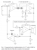
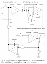
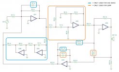
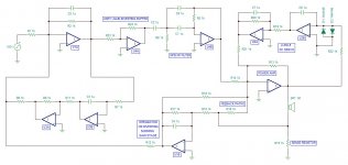
Here is a first stab at a circuit topology that can accommodate both the LEMF and ACE-BASS circuits. Depending on which circuit was desired some components or circuit elements are eliminated (left as an open circuit) or shorted/bypassed. As shown in the legend at the top right hand corner, for the LEMF variant the orange portions are used and the blue portions deleted. For the ACE-BASS circuit the blue parts are used and the orange deleted, except for the large central orange block which is simply bypassed.
The LEMF circuit is for the version that is used to increase driver Q. The version to decrease Q only varies by the feedback connection to the power amplifier section, IOP4.
The LEMF circuit is for the version that is used to increase driver Q. The version to decrease Q only varies by the feedback connection to the power amplifier section, IOP4.
Attachments

Yeah I bought one of those once just to check it out. What a piece of crap. 
...but I do like the concept!
The parallel TDA7293 is more about using what I've got. I'm now thinking that I should separate the project over two boards - one for the amplifier and the other for the ACE-BASS and LEMF circuit. That way each can be built and re-used independently.
...but I do like the concept!
The parallel TDA7293 is more about using what I've got. I'm now thinking that I should separate the project over two boards - one for the amplifier and the other for the ACE-BASS and LEMF circuit. That way each can be built and re-used independently.
Last edited:
Still enjoying my JBL K140 in a 57 liter vented enclosure every day !
I use the 3 op amp version well described on this forum .
Had to replace my DC protection relay as the contacts played up recently .
But so far no complains , the bass is amazing ! -3dB at 17hz and plenty of punch !
My mains are 15 inch Tannoy DC's , not bass shy at all , but the sub is "the finishing touch"
Good idea to use multiple parallel'd chipamps , my sub sound improved a lot when I upgraded the power amp to 400 watts .
Don't forget to drive your acebass with a high pass filter with a Q of 2 at fBox as mentioned in the original Stahl paper .
Good luck and eager to see your results !
Cheers ,
Rens
Last edited:
That's only true if you plan to use the 6th order Butterworth alignment, although that is certainly a good one.Don't forget to drive your acebass with a high pass filter with a Q of 2 at fBox as mentioned in the original Stahl paper.
The Mellow paper presents tables for for 5th and 6th order alignments such as Synchronous, Bessel, B3^2, Butterworth, and Chebychev with ripple 0.1dB, 0.5dB and 1dB. The B^3 looks very interesting in fact.
Interesting thread ... will follow
My own projects have been stalled for some time .... but hope to do updates soon on SW with AceBass and Class-d amp
Hey Baldin,
Welcome, and thanks for dropping by my thread. I see you mentioned using Ace-Bass and a Class-D amp for a subwoofer... I have also been considering a similar project using high-Bl pro drivers after reading this paper by Don Keele:
"Comparison of Direct-Radiator Loudspeaker System Nominal Power Efficiency vs. True Efficiency with High-Bl Drivers," presented at the 115th Convention of the Audio Engineering Society, New York (Oct. 2003). Many thanks to Don for making this convention paper available to the public through his web site (along with lots of other good works of his).
From what I can understand from Keele's paper, the high Bl driver he uses as an example has a high magnitude, and "wide" in terms of frequency, resonance peak that tops out over 1000 ohms. Because the impedance magnitude is so high, the current draw is very low and thus the true "delivered" power is also quite low. Despite the drooping bass response that must be EQ'd flat (e.g. with ACE-BASS or LEMF) the efficiency is very high over a wide range of frequencies. Although Keele doesn't specifically state it, I get the idea that the high Bl factor is causing the driver Qes (and thus Qts) to be very low and that the low Q of the driver's resonance is what is making the impedance peak so broad and tall, NOT the Bl factor itself. Bl is just a means to an end I think.
Anyway, the reason that I am mentioning the Keele paper it is that he specifically mentions that a class-D amp will both deliver and receive energy from the load, to and from the power supply, and that this also contributes to the efficiency. Since either ACE-BASS (using positive feedback) or LEMF (using negative feedback) could be used to EQ the response, this might be an interesting system to investigate. The high efficiency could be very useful for a subwoofer, in contrast to the higher Qts, low Fs, low efficiency subwoofers drivers that are more commonly used.
I'm looking into some low-Q high Bl pro drivers for this purpose, but they are on the order of $400 so I will likely wait until I have done some trials using drivers that I already own.
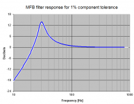
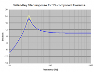
I have been thinking about the part of the circuit used for the LEMF that is a second order HP filter. Mellow used the well-known Sallen-Key topology for this. That's a really bad choice when you are using anything more than very modest values for Q. Mellow's circuit can sometimes require very high Q values up to 10 or more, and this would be problematic for SK. This is because the the circuit response around the max boost at high Q is very sensitive to the component values. I did some Monte Carlo type analysis of this a couple of years ago in Excel as part of some filter design that I was doing.
Here is an example for Q=5. The two attachments are for the Sallen Key topology, and the Multiple Feedback topology. The latter requires more one capacitor but has superior sensitivity (is much less sensitive to component values being slightly different than those required) compared to the SK topology.
As you can see, the SK has a variation of greater than +/-3dB at the peak of the filter response. That's like applying twice or half the power, and this is right around resonance so this difference is important. In contrast the MFB topology has less than 1dB variation in the response. All of these examples were generated assuming a 1% random variation around the optimum component values.
Now that this has come to light I plan to replace the SK HP filter section with a MFB filter. I will add one more op amp because the MFB topology is inverting and by adding a unity gain inverter I can restore the correct polarity. I will also need to make some corrections in the formulas for calculating the other LEMF components. Hopefully I can figure these out with a little thought.
The ACE-BASS version of the circuit remains unchanged.
Attachments
Along with the change to MFB for the HP filter, I have also added a DC servo. Since the LEMF circuit uses an integrator I want to make sure that the amp has a low DC offset. Stahl shows a very large (>100uF) cap on the input to the amplifier in one of the versions of his circuit, but the DC servo should perform better than a large bipolar cap.
With the above changes, the circuit is looking something like this. Keep in mind that both ACE-BASS and LEMF are combined in what is shown, and as before some sections or components of the circuit must be omitted or bypassed to give one or the other.
The way the circuit is laid out makes for easy use of dual op-amp ICs, and I have indicated this on the diagram. When a portion of the circuit is omitted, both amps in that dual op-amp package can be omitted, for instance U3A and U3B, or U4A and U4B.
Attachments
TDA7293's have a linear capacity of 45 watts per chip, although they do allow peaks higher than that.
If there was 8 chips arranged into two of 4-chip parallel amplifier boards and those two boards are bridged, linear capacity is 280W to 8R or 360W to 4R. So, if operated beyond 360W with the 4R speaker it probably will ride the limiter and quiet the bottom octaves to stay within approximately 360W.
If this is too much power, the LTP soft clipper accessory can be used and aligned to the maximum capacity of a specific woofer, in order to prevent x-max noise.
For excellent stability, you'd need the gain up near 40X.
And also you'd need some 100u~270u range (I use 220u) caps for power decoupling, located as close as possible to the master chip's pins 7 and 8. Several parallel 270u per rail can be used if you want to maximize for dynamic punch, but it doesn't tolerate larger amp board power decoupling caps without stability trouble.
For the feedback-shunt RC, starting with 2k7 to 240u as a baseline (BASSline?), if you divide the resistor, multiply the cap likewise. That will maintain working bass amplification for even the lowest notes. If very large cap values result, it may be helpful to employ a DC tracker instead of a huge cap.
To figure the bootstrap cap for a master/slave parallel amp, multiply 33uF times the number of chips.
It is a good practice to heatsink the chip before soldering it.
Along with the change to MFB for the HP filter, I have also added a DC servo. Since the LEMF circuit uses an integrator I want to make sure that the amp has a low DC offset. Stahl shows a very large (>100uF) cap on the input to the amplifier in one of the versions of his circuit, but the DC servo should perform better than a large bipolar cap.
With the above changes, the circuit is looking something like this. Keep in mind that both ACE-BASS and LEMF are combined in what is shown, and as before some sections or components of the circuit must be omitted or bypassed to give one or the other.
The way the circuit is laid out makes for easy use of dual op-amp ICs, and I have indicated this on the diagram. When a portion of the circuit is omitted, both amps in that dual op-amp package can be omitted, for instance U3A and U3B, or U4A and U4B.
very interesting , but a bit confused by R15
, I use .2 ohms ,1k would never work .
Cheers ,
Rens
very interesting , but a bit confused by R15
, I use .2 ohms ,1k would never work
You don't like my implementation using exclusively 1uF caps and 1k resistors??? I got a great deal on a few thousand of these so, you know, might as well put them to use...
As kevinkr noticed, I have drawn the schematic but not (yet) assigned any meaningful values to the components. I'm working out the topology at this point. Keep in mind that it's not possible to provide all the correct values without knowing the exact driver, enclosure, and alignment that one is using, so most of these will remain placeholders until a specific example is given.
Last edited:
TDA7293's have a linear capacity of 45 watts per chip, although they do allow peaks higher than that.
That's not what the datasheet says... see for instance Figure 10. What's your basis for this power spec claim? I can see that this may be true but only in the case of rail voltages that are around +/-30V or so. That's much less than what the ICs can work from.
For excellent stability, you'd need the gain up near 40X.
And also you'd need some 100u~270u range (I use 220u) caps for power decoupling, located as close as possible to the master chip's pins 7 and 8. Several parallel 270u per rail can be used if you want to maximize for dynamic punch, but it doesn't tolerate larger amp board power decoupling caps without stability trouble.
To figure the bootstrap cap for a master/slave parallel amp, multiply 33uF times the number of chips.
It is a good practice to heatsink the chip before soldering it.
Thanks for the above comments on the design details, especially the suggested gain although that seems a bit high.
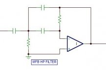
I took a look at the LEMF formulas that involve the second order HP filter. It turns out that using a MFB filter topology instead of the SK type actually simplifies a few things. This is because the gain of the MFB filter can be independently prescribed, whereas for the equal-C, equal-R SK filter that Mellow chose to use the Q is determined by the filter gain, which was factored into the rest of the equations. This gain can be set to 1 for the MFB filter, simplifying the formulas somewhat.
When the gain of the MFB HP filter is set to unity, all three capacitors in the filter circuit take on identical values, and these can be specified at whatever value is convenient. Its the remaining two resistors in the circuit that completely determine the corner frequency and Q and this makes it easy to closely realize the desired transfer function with this topology.
One issue to pay attention to is the value of the shunt resistor on the filter input - it can become quite low in value if Q must be high. The other resistor can be quite high in value, but this is not generally a problem, only a potential noise source. Both resistor values scale up and down with the value selected for the three capacitors, and the shunt resistor might be as low as 1k Ohm. It's therefore important to make sure that the previous stage is not overloaded with current demand. Just something to keep in mind.
MFB HP filter circuit is attached for those who are not familiar with it.
Attachments
- Home
- Amplifiers
- Chip Amps
- The many parallel-TDA7293 ACE-BASS amp project