.
<< You only get one ground and that's the Main Audio Ground point. >>
<< All of which commits pretty serious violence upon the rule of "One circuit, one ground, always and only." I'd actually much rather refer to a signal common, and a chassis common, therefore calling the Main Ground simply ground. But it appears popular usage decides otherwise... >>
Yeah I got that, but thanks for mentioning.
.
Last edited:
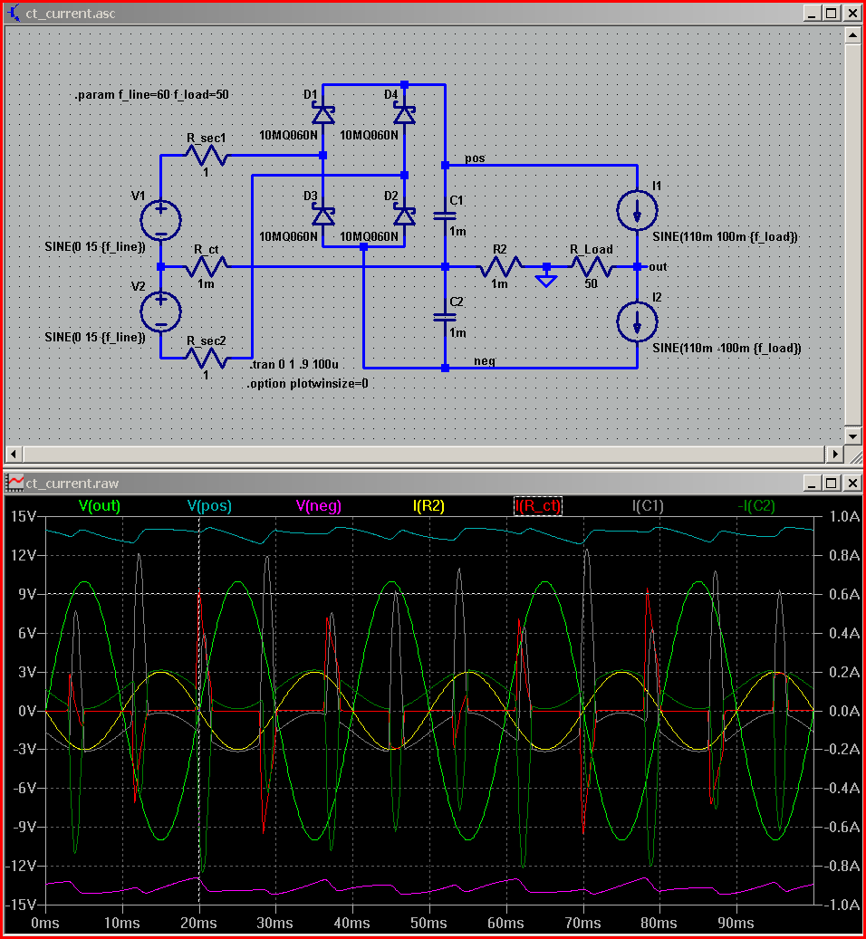
Let us see if we can improve the current supply to the amp. The problem with the long leads from the bypass caps to GND is their inductance, forming a low pass filter. This makes the caps ineffective at 1-10 MHz. You need to make very short (low inductance) connections to a local ground to improve things.
Attachments
Last edited:
.
<< The problem with the long leads from the bypass caps to GND is their inductance...You need to make very short (low inductance) connections to a local ground to improve things >>
I wonder if the polite fiction of a "local ground" might not cause more problems than it wants to solve.
At least everybody agrees (mostly) that there is one and only one real ground point, that being the center tap of the supply transformer. No screaming matches there.
But obviously there must be more than one connection to the ground point, since more than one component requires a ground. Enter the brothers Grimm, accompanied by their large staff of assistants.
Everything begins with one bypass cap connecting to one conductor, which then connects to ground (the one and only real ground). What happens next is what tells the tale.
If the next thing that happens is connecting a second bypass cap--or anything at all--to that same conductor, then it's no longer simply a conductor, it's now a bus. In this particular context it's a ground bus. Of course connecting a third, or however many, additional components doesn't change anything, the conductor remains a ground bus.
All of which is exactly opposite to a star ground, which is, by definition, one component connected to one conductor, which then connects to ground.
As a matter of fact I don't mean to condemn the ground bus concept, as far as I'm concerned the jury is still out on that. But I do mean to say that the fairy tale of a "local ground," aside from being self-deceiving, can cause harm instead of good.
It's self-deceiving because a ground bus is what it is: a single conductor grounding many components. Taking off a branch and making up a name for it like "local ground" doesn't change reality, a ground bus is still a ground bus.
The potential harm is one of the things the star ground was developed to prevent: strong inductive fields caused by addition of currents.
Bypass caps are not exactly high current devices, they work in the range of microamps on down. Inductance depends on magnetic fields, and magnetic fields depend on current flow, so the inductive effect of a conductor carrying less-than-microamps is small.
However, currents can add together, as anybody knows, and this can happen in a ground bus. The result can be a ground bus carrying significant current, causing a significant magnetic field around the conductor, resulting in exactly the inductive effect you were trying to avoid in the first place.
Again I'm not trying to say yea/nay to bus/star. I am saying there's no such thing as a "local ground," while adding a reminder that star grounds were developed to solve a problem that the ground bus created.
.
Last edited:
It would be hard to find a worse ground point than the transfomer CT!bentsnake said:At least everybody agrees (mostly) that there is one and only one real ground point, that being the center tap of the supply transformer. No screaming matches there.
yes a "star", by itself, is exactly a "too simple" idea
hierarchical grounding, "dirty"/"clean" branch separation are important ideas too
and like DF says - CT to reservoir cap junction is "dirty" - has rectified charging current pulsing in the wire, creating nasty nonlinear Vdrop in its R,L
the mains xfmr secondary is floating, the isolation should be taken advantage of by letting it be an "open" end of the dirty current branch
at the very least the location of the "star" point can be chosen for better or worse performance - and worse would be the xfmr CT
“Everything should be made as simple as possible, but no simpler”
hierarchical grounding, "dirty"/"clean" branch separation are important ideas too
and like DF says - CT to reservoir cap junction is "dirty" - has rectified charging current pulsing in the wire, creating nasty nonlinear Vdrop in its R,L
the mains xfmr secondary is floating, the isolation should be taken advantage of by letting it be an "open" end of the dirty current branch
at the very least the location of the "star" point can be chosen for better or worse performance - and worse would be the xfmr CT
Last edited:
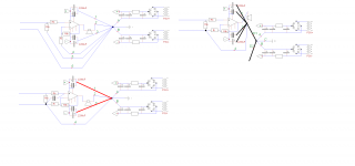
Mark's post42 shows the stages of improvement.
The pic at top right is far better than the earlier, because it gets MUCH LOWER LOOP AREA.
AND
separates the dirty PSU Zero Volts from the Main Audio Ground. Just ONE wire links these two together.
There are two more issues that help with Low LOOP AREA.
The Decoupling supplies most of the current to the amplifier during the first few nanoseconds of a transient demand by the speaker.
That loop includes the amplifier output, the decoupling and the Zobel. The speaker is not yet included because it has too much inductance to be able to draw the instantaneous and fast changing peaks.
Look at the ROUTE the current takes around the loop consisting of the current source, the decoupling (imagine as a battery that can supply 100Apk for 100ns) and the amp and the Zobel and back to the source.
This loop must have low inductance to enable fast transients to pass.
This loop must have VERY SHORT connections.
The junction of the HF & MF decoupling and the Zobel is the Power Ground. That has to go to the Main Audio Ground and then on to the PSU zero Volts.
The second is the link between signal ground and Main Audio Ground.
This should remain close coupled to the flow route that any current here may pass. That means the route with 4 must pass along the line of the input components and along the amp chip (inside which are all the amp components) and along the ground line to the Main Audio Ground.
Last edited:
.
<< At least everybody agrees...that there is one and only one real ground point, that being the center tap of the supply transformer. >>
Whoops. my mistake. Not as much agreement as I'd thought.
.
No center tap transformer in this design.
I also can't help believing that a star ground would be a better option than a multi ground layout, if only it could be done without adding inductance to the supplies of the chip.
.
<< It would be hard to find a worse ground point than the transfomer CT! >>
You miss the point.
<< yes a "star", by itself, is exactly a "too simple" idea >>
You miss the point.
<< I also can't help believing that a star ground would be a better option than a multi ground layout, if only it could be done without adding inductance to the supplies of the chip. >>
It doesn't add inductance. It avoids inductance, which is one reason for using a star ground in the first place. The totaled amount of errors at ground is the same, of course, but a star ground prevents their adding together outside of ground.
OK obviously this is my mistake. I should have been a lot more straightforward. Being that, see next.
.
Last edited:
.
<< The problem with the long leads from the bypass caps to GND is their inductance...You need to make very short (low inductance) connections to a local ground to improve things >>
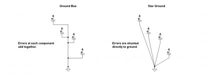
The circuit in post #42 is actually a ground bus, which is used with vacuum tube circuits, but not with op amps.
The reason is that op amps function with very small voltages and currents (except at the output). This makes op amps sensitive to very small voltage or current errors.
The problem with a ground bus is that errors are cumulative. That is, errors at one component can add to the errors of a second component, and this continues down the line.
One effect of this addition can be a relatively large current in the ground bus, which causes the bus to be surrounded by a strong magnetic field. This field, by induction, can inject additional errors right back into the same components, and distortion results.
A star ground prevents this. Errors are shunted directly to ground so there is no cumulative effect.
.
<< The problem with the long leads from the bypass caps to GND is their inductance...You need to make very short (low inductance) connections to a local ground to improve things >>
The circuit in post #42 is actually a ground bus, which is used with vacuum tube circuits, but not with op amps.
The reason is that op amps function with very small voltages and currents (except at the output). This makes op amps sensitive to very small voltage or current errors.
The problem with a ground bus is that errors are cumulative. That is, errors at one component can add to the errors of a second component, and this continues down the line.
One effect of this addition can be a relatively large current in the ground bus, which causes the bus to be surrounded by a strong magnetic field. This field, by induction, can inject additional errors right back into the same components, and distortion results.
A star ground prevents this. Errors are shunted directly to ground so there is no cumulative effect.
.
Attachments
Please can we get rid of this erroneous 'sending errors/noise/interference to ground' paradigm? It leads lots of newbies astray, as well as others who perhaps ought to know better.bentsnake said:A star ground prevents this. Errors are shunted directly to ground so there is no cumulative effect.
'Ground' is merely a voltage reference point, as all voltages need two points. 'Ground' cannot absorb anything, as it is merely a circuit node. Kirchoff tells us that the sum of currents at that point (like any other point) equal zero, so any current coming in on one wire must go out some other wire.
A correctly designed ground bus can be better than a star e.g. in a PSU. It requires thought, of course, while a simple star does not - which may be why people often prefer a star. Stars create the problem of long ground wires back to the star, which have unwanted inductance and resistance. Any technique may involve currents which may cause induction so circuit loops need to be small.
That is why a bus needs to be designed. In particular, the order of connections to it. Get this right and it can be better than a star, in some circumstances.The problem with a ground bus is that errors are cumulative. That is, errors at one component can add to the errors of a second component, and this continues down the line.
.
<< A correctly designed ground bus can be better than a star >>
Well then, what is a correctly designed ground? Or better, how do you design it? If you won't reveal this, then all your statement can possible do is confuse and frighten the newbies you worry about.
In referring to Kirchoff's law you neglect induction, which adds currents not supplied by the transformer. These currents we generically call "noise'" If your argument is to be valid you'll have to explain where the noise goes--since that's the point in the first place.
<< Stars create the problem of long ground wires back to the star, which have unwanted inductance and resistance. >>
This is obviously not so. You should read post #51 at least 3 more times.
While you're studying, consider that the minimum distance from any component to ground is fixed. What kind of ground is used doesn't enter in.
<< get rid of this erroneous 'sending errors/noise/interference to ground' paradigm >>
You can't possibly mean "paradigm." Or if you do, then thanks for the kind words.
However, taking your meaning from the context, your argument is with my sources, which as I've said are Douglas Self, and the engineering department of Texas International. No doubt they'll be glad to receive your corrections.
.
Last edited:
A correctly designed ground is one which takes account of where the currents flow, as I have said here and elsewhere. I am not concealing anything, so I have nothing to "reveal". Ground design is an application of circuit theory - I can't teach circuit theory in a few posts! I am not trying to "confuse and frighten" newbies; on the contrary I am trying to set them free from blindly following recipes, especially faulty recipes.bentsnake said:Well then, what is a correctly designed ground? Or better, how do you design it? If you won't reveal this, then all your statement can possible do is confuse and frighten the newbies you worry about.
You may call induced currents "noise". Most of us call them 'interference' and reserve 'noise' for random noise.These currents we generically call "noise'"
My experience is that people telling me that I am arguing with their sources often turn out to have misunderstood their sources. Sources can be wrong; I recall seeing an application note (I forget who from) which simple repeated audiophile myths about diode and cap bypassing, grounding etc. for audio PSUs - presumably written by a couple of youngsters fresh out of college.your argument is with my sources
Doug Self appears on here from time to time so he can put me straight, if necessary.
.
<< people telling me that I am arguing with their sources often turn out to have misunderstood their sources. >>
This was my point in the beginning. I sometimes think people don't read these threads, they just look at the pictures.
<< A correctly designed ground is one which takes account of where the currents flow, as I have said here and elsewhere...I can't teach circuit theory in a few posts >>
Then why bring up the subject at all? This is telling people they're wrong, but not telling them how to be right. I can't see how this helps anybody.
.
.
<< In referring to Kirchoff's law you neglect induction, which adds currents not supplied by the transformer. These currents we generically call "noise'" If your argument is to be valid you'll have to explain where the noise goes--since that's the point in the first place. >>
<< You may call induced currents "noise". Most of us call them 'interference' and reserve 'noise' for random noise. >>
Call it anything you like. Still waiting to find out how a ground bus fixes the problem, while a star ground doesn't. What happens to the interference?
Hint: swamped. Additional hint: lots of inductance, and lots of capacitance. Further hint: neither transformers nor capacitors are perfect in the first place.
.
Last edited:
Member
Joined 2009
Paid Member
My approach to Grounds are this:
As DF96 says, voltages are always relative, you have a voltage between two points.
I start with the signal. It comes into the amplifier as a voltage difference between two conductors (whether RCA or balanced). I use single ended RCA interconnects and so by convention as much as anything I designate the outer conductor as my reference point. All voltages are then defined relative to the outer conductor of the incoming signal. In other words, the Ground is defined as my signal ground.
I have other points in the circuit that by design, should be at Ground, i.e. there should be no voltage between these various Ground points and my signal ground at the RCA connector. To ensure that this is the case I need to ensure there are no voltage drops along the conductors connecting these points - which as DF96 points out, leads to a consideration of where currents are flowing.
Large currents flow through the power supply - output stage of the amplifier and the speaker. Most amplifier designs require one side of the speaker to be at Ground. This implies that there is a point in the power supply that must also be at Ground. So all these high current points must be connected together with low impedance wiring (short beefy wires) to avoid any voltage drops and they must also be connected to the signal ground without any voltage drops. One way to achieve this is a 'star ground'. It works pretty swell. And you can layer the different connections at the 'star ground' point so that the large ground return currents (from the speaker and power supply filter capacitors) do not contaminate smaller signal return currents.
There is also a need to have your AC Mains safety earth connected directly to the metal chasis. This is not your signal Ground. For safety, you want to connect your signal ground to the chasis too so that any faults that put mains into your circuit will find a way back to the mains safety earth. To avoid hum (from dreaded ground loops) it is common to place a pair of paralleled reversed diodes (i.e. the two diodes are 'pointing' in opposite directions) between the signal ground and the chasis. This provides some isolation or 'ground lift' for the signal ground but still ensures fault current can flow to the chasis - so use beefy diodes that won't burn out in a fault situation before the mains fuse blows.
Last edited:
.
<< ...As DF96 says...as DF96 points out...a 'star ground'. It works pretty swell... >>
What's all this? Remaining dispassionate? Weighing both side of an argument? Willing to grant credence? I almost seem to detect...peacemaking?
Admirable, Bigun! But sadly, pretty much foreordained to fail. Around here all threads tend to degenerate into I'm-right-you're-wrong screaming matches. Admittedly this leaves the forgotten original poster wandering around glassy eyed, wondering what's what, but we all get to show off how smart we think we are, and that's the important thing.
Nice try, though. And blessed are the peacemakers, so that's something.
.
Here is Distortion In Power Amplifiers
Chapter 5.5 discusses decoupling (bypass).
I think it describes the way I have done the layout in post 42.
A local star ground per channel with a connection per channel to the PSU ground. Also how the input and feedback grounds are kept separate from the bypass ground.
I also looked on internet for PCB layouts or amp layouts of D. Self designs and could not find one that used a star ground in the way described by bentsnake.
Last edited:
Member
Joined 2009
Paid Member
.
But sadly, pretty much foreordained to fail.
There are a few folk around here who are perceived poorly (i.e. curt, condescending, argumentative, etc.) at times because of how they write - same trouble I see with email at my work place, it takes some effort to overcome the lack of face-to-face. I am not naive enough to try to be a peacemaker but I do try to write things so as to avoid adverse reactions (unless I'm feeling in the mood for it !!!!
 )
)- Status
- This old topic is closed. If you want to reopen this topic, contact a moderator using the "Report Post" button.
- Home
- Amplifiers
- Chip Amps
- Internal wiring for ChipAmp, Silver? Copper? Gold plated? Thickness?