I could be that this does not have any impact ?
Replacing a 4,700 with a 33,000 no difference ?
Who sad that?
As posted before here you can find calculations here about required size.
Hi and thanks, but also using very high uF value for caps ?
I could be that this does not have any impact ?
Replacing a 4,700 with a 33,000 no difference ?
I am surprised ... really.
Thanks and regards,
gino
Of course a capacitance change "can" make a difference. But it depends on the rail voltage and the attempted signal, and also the amplifier and transformer to some extent, in addition to the caps. The difference it makes is probably like a curve that increases rapidly for a while and then slowly approaches a horizontal line. After you get "enough" capacitance, and especially after you get above the capacitance that makes the system unable to clip, the additional improvement from adding more capacitance will eventually be inaudible (and also not worth any added expense).
You can make the capacitor voltage sags look identical, as a proportion of the rail voltage, by adjusting the other variables.
The voltage sag usually has only a small effect on the sound quality, until it causes the amplifier's dropout or clipping voltage range to be violated, interrupting the output current waveform's shape.
In normal operation, the psu's CURRENT is much more important to sound quality than its voltage, since a class AB power amplifier's output stage's current is directly proportional to the sound that is made by the speakers. For good sound quality, we primarily need good current-delivery quality, from the psu, which means mostly from the capacitors. Click on the link in my signature!
Last edited:
I think what joerytech is trying to look at is the (sound) difference between an amp with a single cap per rail of 1500 uF and an amp with 10000 uF plus local 100 uF per rail.
Audiosector.com and 47 Labs, use low capacitance. Chipamp.com, My_Ref, CarlosFM and most High-end amps use large capacitance. I am convinced both approaches can and do sound great, but why?
There is a load of measuring that could be done. Distortion, gain and phase to name but a very few, It might show some interesting differences, but can it convince anyone which sounds best? Not so easy.
I have a scope and I can't tell by looking at audio signals if its good or bad, its just a squiggly line that moves to the beat of the music.
I have a scope and I can't tell by looking at audio signals if its good or bad, its just a squiggly line that moves to the beat of the music.
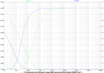
I was actually thinking using a signal generator and use a block-wave to test the slew-rate and a sawtooth wave to see the frequency response with difference cap values
Here I found some info that might be interesting on cap values having effect on the slew-rate of an amp.
Slew rate - Wikipedia, the free encyclopedia
" If the second stage has an effective input capacitance


If I'm correct it means that with higher capacitance the slew-rate (Volts/usec) will be lower.
The capacitance in that equation is not related to the power supply's reservoir capacitance or the decoupling capacitance. It is an internal input capacitance in an amplifier's second stage, loading the output of the first stage. (And that equation is simply the familiar capacitor equation, I = C dv/dt, re-arranged.)
Also, for the power supply and decoupling caps, remember that we only care about the slew rate of the CURRENT that they can supply, since the current that is allowed to flow into the power amplifier output stage's power supply connection is the music signal that goes to the speakers.
I did some work on this, a while back. Some of it is discussed at http://www.diyaudio.com/forums/powe...lm-caps-electrolytic-caps-22.html#post2788202 .
I found that the initial (first few microseconds) rate of current discharge from a capacitor only depends on the ESR of the cap (plus any other resistance in series with the current path) and the change in the voltage across the cap. The transient current that flows, initially, is simply the voltage change divided by the resistance, and does NOT depend on the capacitance value. (Still need to investigate current's transient response for large values of reservoir capacitance, i.e. very little rail-voltage change. Initial current slew rate could be lower, unless other factors compensate. But also, perhaps we never get close to being "too slow", in which case it wouldn't matter.) After the first few microseconds, there is some maximum current discharge rate that stabilizes, which is larger for larger capacitances.
In order to go from zero current to that initial transient current, there is a very short transition time when the cap's output current changes. The speed of THAT change probably depends mostly on the parasitic inductance of the cap and the conductors.
In order to not help degrade the transient response of an amplifier system, there should be decoupling capacitors from rail to ground, very close to the point of load. The decoupling caps should have an ESR that is very low, for maximum transient current capability. And the inductance should be low, for minimum response time. The distance from the point of load and the physical lead spacing of the cap(s) will be the main causes of any inductance. To get lower ESR and low ESL, we should consider using multiple caps in parallel.
The decoupling capacitance needs to be large-enough to supply the current for fast transients, which might not be able to be accurately reproduced if the current had to come through the inductance of the reservoir caps and the power rail conductors. Farther along in the above-linked thread, I started deriving equations for calculating the minimum required decoupling capacitance and their maximum tolerable distance from the point of load. But then I continued the effort in several other threads, I think.
But for something like an LM3886, I would just use an absolute minimum of 470 uF, at each power pin (within a half centimeter). Or, if you used five 100 uF caps, for example, you could put some of them a little farther away and would probably still get lower ESR and ESL than one 470 uF very close to the power pin.
I would use more than 470 uF. I would just pack as many smaller electrolytic caps as possible as close to the power pins as possible, and keep going, using larger-and-larger caps as I got farther away from the power pins, until I had at least the minimum capacitance required to prevent clipping at the rated max output power level, and then connect the rectifiers and transformer, minimizing (almost eliminating) the power rail lengths. (Then we don't really NEED to try to calculate anything, because we've probably done the best we can, unless we want to make a "Terry Given Cap Array" and find a good way to connect it; maybe back-to-back two-layer PCBs?)
Last edited:
Hi, i had the feeling that the sense of some messages was in this direction
I believe much more to instrument than calculation for one reason.
Calculations are valid only under some assumptions.
Let me be trivial please

There is an ideal behaviour. The more the real behaviour differs from ideal the worse.
The ideal behaviour is a voltage at the PS caps that does not change even during more powerful passages.
If this voltage fluctuates a lot this is very far from ideal.
If it varies very little is closer to ideal.
And this is obviously related to quantity and also GRADE of PS caps.
I am so sure about the importance of this measurement that i would increase quality and quantity of the uF in the power supply to reach the goal of a substantial constance on this PS voltage.
The fact that many commercial amps are far from the ideal is extremely telling on their actual quality. Very low indeed.
You should try to put 2 * 60,000 uF in the PS and listen ... impressive.
I did it. I would not go with less uF.
thanks and regards,
gino
Of course a capacitance change "can" make a difference. But it depends on the rail voltage and the attempted signal, and also the amplifier and transformer to some extent, in addition to the caps. The difference it makes is probably like a curve that increases rapidly for a while and then slowly approaches a horizontal line.
After you get "enough" capacitance, and especially after you get above the capacitance that makes the system unable to clip, the additional improvement from adding more capacitance will eventually be inaudible (and also not worth any added expense).
You can make the capacitor voltage sags look identical, as a proportion of the rail voltage, by adjusting the other variables.
The voltage sag usually has only a small effect on the sound quality, until it causes the amplifier's dropout or clipping voltage range to be violated, interrupting the output current waveform's shape.
In normal operation, the psu's CURRENT is much more important to sound quality than its voltage, since a class AB power amplifier's output stage's current is directly proportional to the sound that is made by the speakers. For good sound quality, we primarily need good current-delivery quality, from the psu, which means mostly from the capacitors.
Click on the link in my signature!
Thanks a lot for the very interesting explanation
I was just asking ... how many of you have put a voltmeter across the PS caps ?
I got some answers like ... i did it and the voltage sagged a lot
Stop ... this means that the uf were not high enough in quantity and quality
Simple as that.
If with 30,000uF the needle dances and with 60,000uF dances less, 60 is better than 30.
Not only .... you can also see very easily if solutions like paralleling many smaller caps instead of few big ones really work.
What there is of more convincing than the needle of a voltmeter ? if it stays stable OK
If it dances with the music it could be nicer to look at .... but surely not good at all.
Please tell me if i miss something.
First you can calculate, simulate etc.
But at some point after that you have to measure.
Even if someone keeps on telling that measurements tell nothing. The say.
Maybe they can put two fingers on the caps and test for any voltage drop ...
Thanks again and regards,
gino
Last edited:
You will see a more revealing picture if you connect an AC coupled scope probe across the PSU capacitors and compare to the variations across the amplifier power pins using the other channel on the scope.
The variations at the amp will be bigger and steeper (faster) than the variations at the PSU, due to the impedance of the intervening cables.
The use of adequate and correctly selected (and located) decoupling will supply much of the transient demand of the speakers.
The remaining demand is slow transients and recharge current sent from the PSU to the decoupling.
This PSU changing current is, relative to the decoupling, very slow changes in current.
The slow current changes allows non premium capacitors in the PSU to perform very well. The intervening impedance ensures this is the case.
But in my opinion one still needs adequate quantities of PSU capacitance to meet the demands set by the speaker load.
Last edited:
If I understand well the only difference between smoothing caps and decoupling caps is how far/close they are situated from the actual amplifier because if I'm correct in the schematic they are both connected between rails and ground only decoupling caps much closer to the amp?
In this case I think I only have decoupling caps of 2x1500uF because they are connected on the amp board very close to the amp chip, on the PS board there are no caps!?
In the whole amp (2xLM4780) I have only 4x 1500uF caps
In this case I think I only have decoupling caps of 2x1500uF because they are connected on the amp board very close to the amp chip, on the PS board there are no caps!?
In the whole amp (2xLM4780) I have only 4x 1500uF caps
Not quite.
PSU smoothing capacitance stores the charge pulses. i.e. they turn the full wave rectified AC into varying DC.
Decoupling capacitance is where the speaker, or load, gets it's transient current from.
The very fast changes in transient current can only be met by capacitance that has ultra low inductance.
The PSU capacitance can never meet the fastest demands of the load/amplifier.
The decoupling capacitance must be small to keep the inductance down. That results in very low charge storage.
The decoupling MUST be recharged to be able to meet the demand of the next event.
The PSU smoothing with it's varying DC is what recharges the decoupling.
The transformer and rectifier cannot recharge the decoupling because they are OFF for approximately 90% of the operating time.
The PSU smoothing is the sole energy supply to recharge the decoupling during that 90% OFF period.
Okay, again I understand a bit more how things work and I'm very grateful for the very extended explanations done here.
For me this thread is a search for the reason why (many) think a GC reproduces sound signal better with a low capacitance than a higher one.
It might be a hype that is based on a rumor spread one day but to be honest, its too much accepted by so many that I think there must be a reason for it.
From both sides (for and against low capacitance) I see a lots of theories but no actual proof like scope readings from comparisons of input and output signals with block-wave, sawtooth wave, etc. what might be able to shed a light on the statements from both sides.
I want to ask both sides what they think could be a good test to prove who is telling the truth and then I mean a test without theoretical explanations but as clear as listening.
In my humble opinion it should be something like a advanced scope reading from input and output signal.
Ideally those 2 should be identical
Last edited:
Member
Joined 2009
Paid Member
I've also ready people who have said they prefer not to have excessive capacitance not eh rails of their discrete Class AB amplifiers (Hugh Dean of AKSA fame being one of them) and tend to suggest something around 4,700uF to 6,800uF per rail per channel.
Bear in mind that layout/wiring is a big part of the puzzle because low impedance caps are no good if there is too much inductance in the wiring between them and where the current demand is.
Another thought - not having a large amount of capacitance might actually degrade performance slightly and it may turn out that the impact is pleasing to the ears of some people.
I want to ask both sides what they think could be a good test to prove who is telling the truth and then I mean a test without theoretical explanations but as clear as listening.
In my humble opinion it should be something like a advanced scope reading from input and output signal.
Ideally those 2 should be identical
I don't think we're yet at the stage in understanding how power supplies make a difference to the sound of our amps to come up with measurements. Not that the differences can't be measured, rather that we don't know yet what precisely to measure. My best guess is that the future measurement will be one of difference in noise levels on the supply lines - noise differences are very difficult to quantify and FFTs really aren't going to cut it. FFTs aren't optimal for wideband noise measurements, given they always incorporate some averaging. Wavelet transforms are probably called for to get some different trade-offs between time and freq domain.
I've also ready people who have said they prefer not to have excessive capacitance not eh rails of their discrete Class AB amplifiers (Hugh Dean of AKSA fame being one of them) and tend to suggest something around 4,700uF to 6,800uF per rail per channel.
Bear in mind that layout/wiring is a big part of the puzzle because low impedance caps are no good if there is too much inductance in the wiring between them and where the current demand is.
Another thought - not having a large amount of capacitance might actually degrade performance slightly and it may turn out that the impact is pleasing to the ears of some people.
47Labs gaincard has only 1000uF per rail at the chip and none at the PSU.
You will see a more revealing picture if you connect an AC coupled scope probe across the PSU capacitors and compare to the variations across the amplifier power pins using the other channel on the scope.
The variations at the amp will be bigger and steeper (faster) than the variations at the PSU, due to the impedance of the intervening cables.
The use of adequate and correctly selected (and located) decoupling will supply much of the transient demand of the speakers.
The remaining demand is slow transients and recharge current sent from the PSU to the decoupling.
This PSU changing current is, relative to the decoupling, very slow changes in current.
The slow current changes allows non premium capacitors in the PSU to perform very well. The intervening impedance ensures this is the case.
But in my opinion one still needs adequate quantities of PSU capacitance to meet the demands set by the speaker load
Hello and thanks for the advice
I am sure that your procedure is much more telling that the simple test i was thinking of, but i do not know even how to switch on a scope.
I still think that basic tests can be tellling as well to show deviations from an ideal behaviour.
What i was meaning is that in the end the instruments if well used do not lie.
And i always like the instrumental approach that gives evidence of phenomena going on.
I can calculate the right amount of uF and then run in a bad batch, for instance, and fail to get the predicted performance (and the instrument will tell this).
I would even place one of these voltmeters on the front plate.
A failure/lack of performance in the ps caps would be immediately evident.
And i would add uF to get the needle stable, at least at normal listening levels.
When the basic requirements are fulfilled than we can pass to others ...
What is the reason, so to speak, to improve topologies to get the last drop of detail when then the PS voltage sags under pressure ?
And to the people that do not believe in instruments i would just tell that this attitude is unrespectful to famous audio Brands that invest million of dollars in lab instruments.
Thanks againg for your valuable advice
Kind regards,
gino
- Status
- This old topic is closed. If you want to reopen this topic, contact a moderator using the "Report Post" button.
- Home
- Amplifiers
- Chip Amps
- Best capacitance for Gainclone