Sorry that I didn't post here for some time, but unfortunately I had other things to do...
@gootee: I too can't wait to hear any results.
But the most interesting part would be to actually measure any differences compared to a non-paralleled power supply approach, and find out if and how the theory shows its superiority in practice.
And of course, how it sounds.
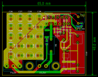
I have redone the amp PCB to hold 10 parallel supply bypass caps per rail.
Therefore I had to increase the PCB height by 12mm to now 49mm.
With the increased height, I had some spare space, so I included options for a 0.1R 5W output series resistor (for paralleling amplifier boards), and the signal input cap can now be 5mm, 22.5mm or 27.5mm pitch.
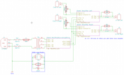
I have also attached my intended wiring scheme.
@gootee: I too can't wait to hear any results.
But the most interesting part would be to actually measure any differences compared to a non-paralleled power supply approach, and find out if and how the theory shows its superiority in practice.
And of course, how it sounds.
I have redone the amp PCB to hold 10 parallel supply bypass caps per rail.
Therefore I had to increase the PCB height by 12mm to now 49mm.
With the increased height, I had some spare space, so I included options for a 0.1R 5W output series resistor (for paralleling amplifier boards), and the signal input cap can now be 5mm, 22.5mm or 27.5mm pitch.
I have also attached my intended wiring scheme.
Attachments
No, I haven't tried it yet, but I will definately do.
But I could only compare using my (non-audiophile I guess) ears.
It would be a lot more interesting to actually measure the performance differences, but unfortunately I don't have the necessary equipment to do this.
If anyone wants to do some serious testing, please feel free to ask for PCB files...
Before I actually build it, I first want to finish all my PCB designs required for the project.
I still need a softstart for the transformer, and a speaker protection.
As I was looking for different solutions, I came across a version with an illuminated pushbutton like this (I find those look very neat).
So I'm just thinking how to implement it.
As I need to power the related logics, I'll use an auxiliary transformer.
The wiring scheme has to change as follows:
The backside power switch (integrated in IEC power inlet) does only power up the auxiliary transformer, and not the main transformer.
On main power-up, the main transformer should always be off.
If I press the pushbutton (to switch on), the main power relay is enganged.
I prefer resistors over thermistors because of the problem with frequent turn-on.
After some time (100 to 300ms I think), the relay for the power resistors is engaged to bypass the resistors.
After some seconds (when the rails have stabilized), the speaker protection switches the output on.
If any failure on the output occurs, the outputs must switch off immediately, as well as on power loss or manual turn-off by pushbutton.
Is there any ready-available project which suits my needs, or do I have to create one from scratch?
I have already selected suitable mains relays: Omron G8P-1A4P 12V.
SPST, 250V @ 30A rating, should be sufficient for any transformer one should ever select to power an amp, I think...
I think that there are many already-available projects, for those. Have you looked at Rod Elliot's ESP site?
Elliott Sound Products - The Audio Pages (Main Index)
Maybe this one:
Loudspeaker Protection and Muting
and this one:
Soft-Start Circuit For Power Amps
Also, do some searches here at diyaudio and see what others have done, and what they think of the circuits I linked-to, above. I have not personally used those circuits. But I tend to trust Rod Elliot, more than most.
P.S. Remember that you want to protect the speakers. You can't protect the silicon. It's best to not try. i.e. Fuses should not be anywhere after the rectifiers, since their resistance changes according the the current through them and they will therefore increase the system's non-linearity.
Last edited:
Yes, I have looked at Rod Elliott's site.
It is quite informative, and I think I will use the hints and calculations provided here.
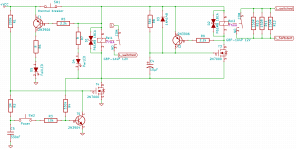
For the soft start circuit, I will use the schematics in figure 2, combined with the altered pushbutton control of the Epsilon24.
I have increased the delay time for the second relay to 100ms, maybe it must be increased even a little more.
The simulations look quite well, I have attached my current schematics.
I know that I cannot protect silicon with a fuse, so I want to handle my silicon well.
The protection circuit from ESP looks good too, but one detail makes me worry a little.
Elliott writes that, to prevent an arc in case of a fault, the NC contact of the speaker relay should be wired to ground. So an arc can extinguish easier and does not weld the contacts together.
In principle, I agree with that.
But: Due to the muting circuit included in the design, if a signal is applied to the amplifier at turn-on, that leads to a full short circuit until the relay switches the speaker output on!
Hopefully the short circuit protection of the chip kicks in to save it, and that at every power-on.
Not nice for the silicon...
It is quite informative, and I think I will use the hints and calculations provided here.
For the soft start circuit, I will use the schematics in figure 2, combined with the altered pushbutton control of the Epsilon24.
I have increased the delay time for the second relay to 100ms, maybe it must be increased even a little more.
The simulations look quite well, I have attached my current schematics.
I know that I cannot protect silicon with a fuse, so I want to handle my silicon well.
The protection circuit from ESP looks good too, but one detail makes me worry a little.
Elliott writes that, to prevent an arc in case of a fault, the NC contact of the speaker relay should be wired to ground. So an arc can extinguish easier and does not weld the contacts together.
In principle, I agree with that.
But: Due to the muting circuit included in the design, if a signal is applied to the amplifier at turn-on, that leads to a full short circuit until the relay switches the speaker output on!
Hopefully the short circuit protection of the chip kicks in to save it, and that at every power-on.
Not nice for the silicon...
Attachments
Instead of a dead short when the relay is to ground, use a dummy load resistor, so that the amplifier sees a load. When in mute condition, the amp output will not mind seeing a load at half, maybe even as low as one quarter, of nominal rated load impedance. Try a 2r2 with the input shorted and see what the amplifier does...............................Elliott writes that, to prevent an arc in case of a fault, the NC contact of the speaker relay should be wired to ground. So an arc can extinguish easier and does not weld the contacts together.
In principle, I agree with that.
But: Due to the muting circuit included in the design, if a signal is applied to the amplifier at turn-on, that leads to a full short circuit until the relay switches the speaker output on!..............
- Status
- This old topic is closed. If you want to reopen this topic, contact a moderator using the "Report Post" button.
- Home
- Amplifiers
- Chip Amps
- LM3886 component selection