That sounds like a workable idea. However, most cringe at the idea of having any open segment or port that increases the chance for the liquid to find the electronics. If one were to do an umbilical two unit system (like Andrew suggests) that separation would avoid the risk. Something to try down the road.
Thanks for splashing around,")
Thanks for splashing around,
Last edited:
hi BcmBob,
The link you sent didn't want to open the page but I went on the forums and found it ,lol.
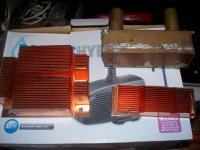
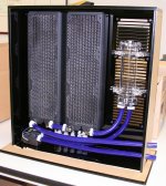
What a nice site WATER Cooling who would have thought,lol.just kidding ,I got my start years ago when a AMD 900 cpu was king,I used a dorm refrigerator to cool liquid to a aluminum block we got 3 time the speed out of it and it remained stable ,then we changed to a heatsink with liquid freon boiling off on a spot where the cpu mounted,it took all the voltage we could give it from the MB,and then tried a higher voltage cpu supply ,got five times the speed but not for long,Let the smoke out,lol. The pics are my try at audio amps , I cut server copper heatsinks in half long ways and covered them with copper sheet the in and outs are 1/2" copper tubing,I am using a pond pump runs about 800 gals a hour of water through them I run them in series and only see about 1 degree rise on the second sink,I use a 5 gal bucket for a resavoir and have a radiator that's not hooked up yet because I can play the amps for a while before it heats the water up them I shut down and let it cool ,I have used a radiator before and you can vari the cooling with 2 fans on it works well ,I would like to build a circuit that will track the heat and control the fans ,might use some automotive controls if I can't find a simple circuit to do this,lol.
Happt Listening!
NS
The link you sent didn't want to open the page but I went on the forums and found it ,lol.
What a nice site WATER Cooling who would have thought,lol.just kidding ,I got my start years ago when a AMD 900 cpu was king,I used a dorm refrigerator to cool liquid to a aluminum block we got 3 time the speed out of it and it remained stable ,then we changed to a heatsink with liquid freon boiling off on a spot where the cpu mounted,it took all the voltage we could give it from the MB,and then tried a higher voltage cpu supply ,got five times the speed but not for long,Let the smoke out,lol. The pics are my try at audio amps , I cut server copper heatsinks in half long ways and covered them with copper sheet the in and outs are 1/2" copper tubing,I am using a pond pump runs about 800 gals a hour of water through them I run them in series and only see about 1 degree rise on the second sink,I use a 5 gal bucket for a resavoir and have a radiator that's not hooked up yet because I can play the amps for a while before it heats the water up them I shut down and let it cool ,I have used a radiator before and you can vari the cooling with 2 fans on it works well ,I would like to build a circuit that will track the heat and control the fans ,might use some automotive controls if I can't find a simple circuit to do this,lol.
Happt Listening!
NS
Attachments
I understand the like for home built solutions, and the fun. but for those wanting to get into it with a little less hassle, try one of these
Google Image Result for http://www.xbitlabs.com/images/news/2011-10/intel_coolers.jpg
Google Image Result for http://www.xbitlabs.com/images/news/2011-10/intel_coolers.jpg

Last edited:
Just want to clear any misconceptions about watercooling.
You dont need to "hold" water in the radiator to cool it, because when you think about it, you are also "holding" it longer to be heated up by the load.
The flow rate is not really important at all. This is why.
Imagine a race track. There is a 1km section of black road, and 3km section of white road.
It doesnt matter HOW fast that car goes, it will still spend the exact same amount of time in each section. Sure, it spends less time in each section, but it comes around that much quicker.
This is a very common myth in the watercooling world. (PCs especially)
Its only going towards the very slow flow rates that the LOAD temperature starts to increase. If your water spends so much time in the "heated" zone, it will come out hot, and you cant cool your load to below the temperature of the hottest water.
So slow flow rates approach the situation of a "Stopped" flow rate. Overheating.
So as long as you maintain a fairly decent flow rate, changing the flow rate doesnt make any difference.
Just a question: does anyone considered amp submerging ?
Don't think it is a good idea, because the oil will heat up all the other components that normally wouldn't get that much heat, plus if anything goes wrong good luck cleaning that section.
Can be also done with PC, but also not really a reasonable option.
That particular example doesn't account for heat dissipation. It would require a second system to avoid turning the whole thing into a turkey fryer. The 24 output transistor build I'm doing now is capable of producing almost that amount of energy when biased high. The simple fact that water is extremely efficient at the task keeps me pointed in that direction.
....from ESP article....
"19 - Water Cooling
I was going to stay away from this completely, but it is worth at least a small section. Water just happens to be the best heat removal medium known, with a specific heat of 4.1813 (J / (g·K)), it requires more energy to raise a gram of water by one degree C (or 1 Kelvin) than any other material.
If extremely high power is the goal (and a bit of plumbing is Ok), a water cooled heatsink is the ideal. Provided the thermal resistance from junction to heatsink is minimised, a minuscule heatsink with only a moderate water flow will remove prodigious amounts of heat. Although uncommon for audio amplifiers, water cooling has been used for many years for cooling high power radio transmitters and the like.
However, it must be admitted that few audiophiles will go to the trouble of installing special plumbing to cool their amplifiers - it would be cheaper to put them in another room and use fan cooling, and a lot more convenient.
Having said that, the use of water cooling is gaining in popularity, and quite a few commercial H20 cooling systems are available for microprocessors. As component density increases in the ICs, it becomes harder to get the heat out efficiently, so expect to see that side of the market expand in the next few years. While it must be admitted that water cooled heatsinks are the best possible choice for amplifiers, this is not an area that can be expected to grow, since it is just too expensive and unwieldy to implement. Finding a silent running pump is another hurdle, and although the plumbing is not at all difficult (it's all low pressur), it still has considerable nuisance value - the cables in a typical system are bad enough, let alone having a plumbing system that must be 100% watertight. Of course, then there is the radiator, pump and fan to be considered - they have to live somewhere, and can be expected to have a SAF (Spouse Acceptance Factor) of perhaps -20dB ("I don't know what you're planning to do with that horrible looking thing, but if it comes in here, I'm moving out!" - a fairly typical response, I would suggest).
Still, I may do a water cooled heatsink project at some time, just for the fun of it ;-."
The 24 output transistor build I'm doing now is capable of producing almost that amount of energy when biased high. The simple fact that water is extremely efficient at the task keeps me pointed in that direction.....from ESP article....
"19 - Water Cooling
I was going to stay away from this completely, but it is worth at least a small section. Water just happens to be the best heat removal medium known, with a specific heat of 4.1813 (J / (g·K)), it requires more energy to raise a gram of water by one degree C (or 1 Kelvin) than any other material.
If extremely high power is the goal (and a bit of plumbing is Ok), a water cooled heatsink is the ideal. Provided the thermal resistance from junction to heatsink is minimised, a minuscule heatsink with only a moderate water flow will remove prodigious amounts of heat. Although uncommon for audio amplifiers, water cooling has been used for many years for cooling high power radio transmitters and the like.
However, it must be admitted that few audiophiles will go to the trouble of installing special plumbing to cool their amplifiers - it would be cheaper to put them in another room and use fan cooling, and a lot more convenient.
Having said that, the use of water cooling is gaining in popularity, and quite a few commercial H20 cooling systems are available for microprocessors. As component density increases in the ICs, it becomes harder to get the heat out efficiently, so expect to see that side of the market expand in the next few years. While it must be admitted that water cooled heatsinks are the best possible choice for amplifiers, this is not an area that can be expected to grow, since it is just too expensive and unwieldy to implement. Finding a silent running pump is another hurdle, and although the plumbing is not at all difficult (it's all low pressur), it still has considerable nuisance value - the cables in a typical system are bad enough, let alone having a plumbing system that must be 100% watertight. Of course, then there is the radiator, pump and fan to be considered - they have to live somewhere, and can be expected to have a SAF (Spouse Acceptance Factor) of perhaps -20dB ("I don't know what you're planning to do with that horrible looking thing, but if it comes in here, I'm moving out!" - a fairly typical response, I would suggest).
Still, I may do a water cooled heatsink project at some time, just for the fun of it ;-."
BTW, for those concerned with water cooling and potential fire and electrocution hazards, there are some cooling fluids used in PC cooling that are totally non conductive and non-destructive to electronics...
See here as example
http://www.frozencpu.com/products/14840/ex-liq-201/Fluid_XP_Industrial_Grade_Deionized_Water_-_UV_Invisible_Blue.html?tl=g30c337s888
And this is just one of many brands... Basically, cooloant with deionized water is not conductive.
Ciao!
Do
See here as example
http://www.frozencpu.com/products/14840/ex-liq-201/Fluid_XP_Industrial_Grade_Deionized_Water_-_UV_Invisible_Blue.html?tl=g30c337s888
And this is just one of many brands... Basically, cooloant with deionized water is not conductive.
Ciao!
Do
Hi BcmBob,
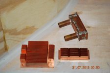
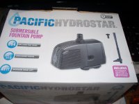
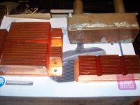
I used this pump it's quiet and at about 260 gals a Hour,I found some solid copper server heatsinks and cut them in half longways,covered them with copper sheet and soldered on 2 1/2" tubes to get the water in and out,I run them on a F5 F5T and a Ba-3 so far I have a pump for all of these(1 Channel) running from f5 to F5t to ba-3 and into a 5 gal bucket of water, depending on TEXAS weather I have a temp probe right beside the mofsets to read out the temp so far the most I have read is 48 C so no radiator yet or a control to regulate the pump speed,NOW it will heat up after a while but is good for a few good songs,lol.
I made you a couple of pics!
Have FUN I do,lol.
NS
Attachments
Hi BcmBob,
I used this pump it's quiet and at about 260 gals a Hour,I found some solid copper server heatsinks and cut them in half longways,covered them with copper sheet and soldered on 2 1/2" tubes to get the water in and out,I run them on a F5 F5T and a Ba-3 so far I have a pump for all of these(1 Channel) running from f5 to F5t to ba-3 and into a 5 gal bucket of water, depending on TEXAS weather I have a temp probe right beside the mofsets to read out the temp so far the most I have read is 48 C so no radiator yet or a control to regulate the pump speed,NOW it will heat up after a while but is good for a few good songs,lol.
I made you a couple of pics!
Have FUN I do,lol.
NS
Nicely Done! Keep coming with the photos as you get the whole system together.
Aleph Kool J
I am following in Bob's footsteps with an attempt to build the diyAudio Store version of the Pass Aleph J using liquid cooling, in particular, my version of Bob's cooling tower approach. I admit to being a very slow project builder, but I've made enough progress to show the liquid cooling heat sink. Besides, Bob has been bugging me to post.
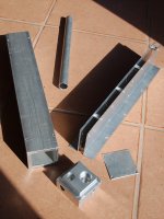
For the heatsink, I am using a 2" square x 1/4" wall thickness aluminum tube. I made a manifold for the base with both inlet and outlet ports. As in Bob's design, the water flows up from the bottom in the square tube, then flows down through a round tube inside to the pump. The height of the round tube is set by the output devices on the square tube. In my case, I have added several inches of square tube above that to serve as a reservoir for fluid and thermal expansion.
In my case, both the square and round tube are press fit to the manifold. I was worried about leaking with a square press fit, so I also welded the manifold to the square tube.
The first photo shows the parts before assembly.
http://www.diyaudio.com/forums/attachment.php?attachmentid=376134&stc=1&d=1381502160
The second photo shows the heatsink assembly during the mockup stage. At this point, I am experimenting with standoff height relative to the output devices. Since there are no through holes in the heatsink above the manifold, any leak should be below the electronics. I will build the rest of the amp with all joints below the electronics. Not that I think there will be any leaks.
http://www.diyaudio.com/forums/attachment.php?attachmentid=376135&stc=1&d=1381502160
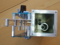
The last photo is a shot down the heatsink tube showing the round tube and port inside. I am sure it will take me a long time to get this puppy running, but I am looking forward to see how well it cools.
http://www.diyaudio.com/forums/attachment.php?attachmentid=376136&stc=1&d=1381502160
If I had it to do over again, I would look for an extruded outer tube with a heavy central wall. The output devices are too large to mount at the edge, so tapping shallow holes in the 1/4" thick wall to secure the output devices can be tricky. (OK, I admit it. I screwed up on on hole.) If you had a central wall, you could tap deeper holes without risk. The other approach is to use a spreader bar that bridges across the output device to the deeper walls at the edges.
I am following in Bob's footsteps with an attempt to build the diyAudio Store version of the Pass Aleph J using liquid cooling, in particular, my version of Bob's cooling tower approach. I admit to being a very slow project builder, but I've made enough progress to show the liquid cooling heat sink. Besides, Bob has been bugging me to post.
For the heatsink, I am using a 2" square x 1/4" wall thickness aluminum tube. I made a manifold for the base with both inlet and outlet ports. As in Bob's design, the water flows up from the bottom in the square tube, then flows down through a round tube inside to the pump. The height of the round tube is set by the output devices on the square tube. In my case, I have added several inches of square tube above that to serve as a reservoir for fluid and thermal expansion.
In my case, both the square and round tube are press fit to the manifold. I was worried about leaking with a square press fit, so I also welded the manifold to the square tube.
The first photo shows the parts before assembly.
http://www.diyaudio.com/forums/attachment.php?attachmentid=376134&stc=1&d=1381502160
The second photo shows the heatsink assembly during the mockup stage. At this point, I am experimenting with standoff height relative to the output devices. Since there are no through holes in the heatsink above the manifold, any leak should be below the electronics. I will build the rest of the amp with all joints below the electronics. Not that I think there will be any leaks.
http://www.diyaudio.com/forums/attachment.php?attachmentid=376135&stc=1&d=1381502160
The last photo is a shot down the heatsink tube showing the round tube and port inside. I am sure it will take me a long time to get this puppy running, but I am looking forward to see how well it cools.
http://www.diyaudio.com/forums/attachment.php?attachmentid=376136&stc=1&d=1381502160
If I had it to do over again, I would look for an extruded outer tube with a heavy central wall. The output devices are too large to mount at the edge, so tapping shallow holes in the 1/4" thick wall to secure the output devices can be tricky. (OK, I admit it. I screwed up on on hole.) If you had a central wall, you could tap deeper holes without risk. The other approach is to use a spreader bar that bridges across the output device to the deeper walls at the edges.
Attachments
Great Props to both NS and Jac 
I'm thrilled to see other working on the concept.
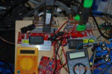
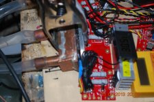
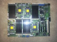
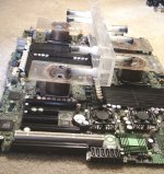
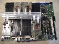
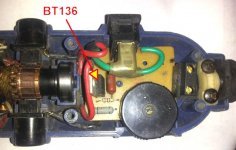
NS - Nice use of PC heatsinks. It would be interesting to see your feed/return layout. I started something similar for a server motherboard that has four quad-core processors on-board. Like you, I used stock materials - the CPU heatsinks are just 1.5" copper pipe caps. I'm showing it here as the manifold approach sounds like something you could apply to your project. Make sure you look into automotive heater cores if/when you add a radiator. I'm still struggling with AC pump speed control but may have found the answer by accident. I have a Dremel type grinder that required occasional re-soldering on the internal PCB. It finally dawned on me that copying that circuit could do the trick. Hope to give it a try soon.
Here is the magic bullet: BT136-600D
DC pumps and fans are much easier to control.
*********
Jac - Nicely done. I bought a small welder but it doesn't have the grunt to do aluminum. You may be receiving some mystery packages in the mail soon.
You are ahead of me as my current inlet and return is made from copper tubes soldered to a piece of flat stock. The block you machined is a clearly superior method. I haven't tried it yet as the thickness needed requires laminating at least two pieces of the Plexiglas I'm using, and I don't want to introduce a potential leak point at that joint. I like the plastic because it machines just like metal with hand tools and many DIYers don't have access to a shop. I have some 2" blocks on order. But your bottom plug design offers great flexibility for taping to match and align tubes in proper orientation for the rest of the cooling system.
Not sure what having a reservoir at the top provides. That implies you may be filling the system from that point. I think it is too close to the FETs to be safe. Please explain. It looks like the combination of the cooler and those mounting devices will supply a big margin of heat dissipation. Looking Good!
I'm thrilled to see other working on the concept.
NS - Nice use of PC heatsinks. It would be interesting to see your feed/return layout. I started something similar for a server motherboard that has four quad-core processors on-board. Like you, I used stock materials - the CPU heatsinks are just 1.5" copper pipe caps. I'm showing it here as the manifold approach sounds like something you could apply to your project. Make sure you look into automotive heater cores if/when you add a radiator. I'm still struggling with AC pump speed control but may have found the answer by accident. I have a Dremel type grinder that required occasional re-soldering on the internal PCB. It finally dawned on me that copying that circuit could do the trick. Hope to give it a try soon.
Here is the magic bullet: BT136-600D
DC pumps and fans are much easier to control.
*********
Jac - Nicely done. I bought a small welder but it doesn't have the grunt to do aluminum. You may be receiving some mystery packages in the mail soon.
You are ahead of me as my current inlet and return is made from copper tubes soldered to a piece of flat stock. The block you machined is a clearly superior method. I haven't tried it yet as the thickness needed requires laminating at least two pieces of the Plexiglas I'm using, and I don't want to introduce a potential leak point at that joint. I like the plastic because it machines just like metal with hand tools and many DIYers don't have access to a shop. I have some 2" blocks on order. But your bottom plug design offers great flexibility for taping to match and align tubes in proper orientation for the rest of the cooling system.
Not sure what having a reservoir at the top provides. That implies you may be filling the system from that point. I think it is too close to the FETs to be safe. Please explain. It looks like the combination of the cooler and those mounting devices will supply a big margin of heat dissipation. Looking Good!
Attachments
Last edited:
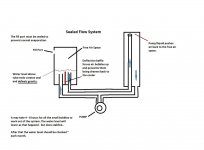
Not sure what having a reservoir at the top provides. That implies you may be filling the system from that point. I think it is too close to the FETs to be safe. Please explain.
I'm probably the one needing an explanation here. I guess I haven't figured out how your reservoir works if it is low. It seemed to me that a low reservoir would have to be sealed to avoid overflowing from the higher water level of the heat exchanger. I thought the air belonged at the top of the system and I could just make the heatsink taller as a reservoir. that way, I can have an overflow weep hole (see small brass tube near the top) and a small hose directing any overflow to the bottom.
As for spilling on the FET, I didn't expect to be filling it that often. I just expected to be careful. Just curious, how much coolant disappears over time in your experience?
I guess now is the time to reconsider a separate reservoir, if that is the right thing to do.
Yes the system needs to be sealed to avoid evaporation loss. You can setup the entire loop -cooler, radiator, resivoir, pump and tubes independently. In fact you should as a safety check. Run it and check for leaks. Stop it and let it set overnight and check. Sometimes the flow masks tiny leaks that gravity will find.
Try to visualize your entire amp system with chassis beforehand. Then you can build the reservoir to your specific requirements. I tend to make them taller than necessary and keep the liquid level high as an evaporation shield. There are a few tricks to getting Plexiglas joints air tight. Just let me know when you get to that point. A small sheet ~ 1/8" - 1/4" from Home Depot will make several reservoirs. It just needs to be thick enough to hold a taped hole. You may have the tools and skills to come up with an aluminum base similar to your cooler bottom. There are many available designs.
It may not make sense at first, but as long as the air is sealed out you can place both the pump and the reservoir at any level and/or location.
Attachments
Last edited:
Hi ALL,
LOOKING GOOD,some new ideas,I like that,
I am going to set up the fan,radiator,pump to cool the water in the reservoir and then let the pumps circulate it through the heatsink coolers,I figure it will keep a constant temp better and I won't have to control the circulating pump speed as my motor/pumps are enclosed units,I am using 10 gals of water now as a res and don't have to cool it ,it stays around 47 C ,I would like to see 50 C as thats the point Nelson sazs is optimum ,I do think it's a good temp to use,I notice that when it heats up to close to that temp it sounds a little better mostly bass punch,maybe that's the temp sweet spot,LOL. Keep it comming,just think a 1000's fet and a heated swimming pool,lol.
Regards,
NS
Jac, After a little thought - your placement of the free air space at the top of the cooler is probably a valid design. It may be a little tricky at first to get the fluid level inside the cooler at a place where air isn't drawn back through the pump, particularly after the flow is stopped for a period of time.
But as you say - much care is needed when filling the system. I'd encourage you to do the first filling without the amp modules - run it - test it. Probably the most significant difference with a remote reservoir from Plexiglas is that is can also act as a sight glass for liquid levels.
There is a tiny bit of microscopic fluid loss through the walls of Tygon type tubing over long lengths. If you can use the metal tubing you mentioned, you may only have to do a check every six months or longer.
Last edited:
http://www.diyaudio.com/forums/attachment.php?attachmentid=391284&stc=1&d=1388705782
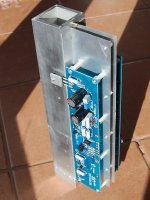
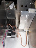
Just a brief update. I've been working on building the box to house the liquid cooled Aleph J.
First of all, it's huge. I know. I'm sure I could make it quite a bit smaller, but I wanted lots of room to change components, tune the bias, etc. And without having to take everything apart.
The component layout was driven by my idea of keeping most of the water connections below the electronics or far away. I was also trying to keep noise as low as possible by having all of the air come in and out on the back. Their will be a second floor that will sit above most of the cooling lines. That allows me to support things like the transformer.
I am using copper line for longevity. My radiator looks tiny compared to those used by Bob, but the specs suggest it will easily handle the 160 W that the AJ has to reject. This is no BA-3 for heat rejection.
More to come, although it is becoming busy at work, so who knows when I will finish it.
Attachments
- Status
- This old topic is closed. If you want to reopen this topic, contact a moderator using the "Report Post" button.
- Home
- Amplifiers
- Chip Amps
- Liquid Cooling Build