Nice work Jac. Your metal work is always so clean and professional. That extra room will come in handy for both the cooling system and tweaking the amp. I know my F5 is over built with 1/2" tubing so it will be interesting to hear how that copper handles the flow volume. Got any info on the pump? looks like it is a pump resavior combo????
Can't see something like a return near the top of the water box. What is your plan?
Can't see something like a return near the top of the water box. What is your plan?
Got any info on the pump? looks like it is a pump resavior combo????
Can't see something like a return near the top of the water box. What is your plan?
The pump is an alphacool VPP655. I picked it because it has speed control on the back. The big black thing on the end is not a reservoir but an impeller housing and manifold from alphacool.
The water box is like your with a tube inside. There are both output and return connections at the bottom. The water flows in through the square tube and out down the internal tube. The main difference is that my water box is taller than the circuit boards, providing some reservoir volume. At the top, there is a tiny bleed hole that connects to a small brass tube. This is the path for overflow and pressure relief and will have a hose that runs down to a collection tray.
I hope that answers your question.
The build for the latest version of the BLAT is shown here. My new favorite material is 1/8" aluminum sheet. With the help of a local shop, Ackerman Bros., much of the structure was attained with simple 90 degree bends. Standard home shop tools - drill, grinder, table saw, portable band saw and FILES  were used. Most fasteners are 6-32 screws through 1" X 1" angle.
 [/url][/IMG]
 [/url][/IMG]
Many of the features on the build have been posted elsewhere so I will omit some of those details here. This amp has 24 output transistors and they can boil water within minutes. The large disk on the water box is a sensor that will shut off the AC mains feed ~ 68 C. The green thermistor is connected to a pump speed control circuit to keep motor noise at a minimum.
 [/url][/IMG]
The cooling system - radiator, fans, pump and water box - was filled and leak tested with an auxiliary power supply. Tubing is a combination of soldered copper and plastic.
 [/url][/IMG]
 [/url][/IMG]
 [/url][/IMG]
All four transformer (500 VA/18) input leads pass through CL-60s and no soft start has been needed - so far....
 [/url][/IMG]
Here is the amp in the sound and temperature test. Readings were taken after 90 minutes of continuous play at max volume from the Walkman.
 [/url][/IMG]
 [/url][/IMG]
The other safety hazard in a LQ build is neglecting to turn the cooling system on - learned that the hard way. With a tip from the "Foam Core Speaker King" - xrk971 - I was able to install a modified 12 VDC wall wart internally. With the cover that PS is one of the warmest (42 C) elements. It is a neat little board and can be mounted bare if it's heat proves to be problematic. Has a nice little LED that might be routed to the front panel later.
 [/url][/IMG]
Top support frame with side standoffs is added.
 [/url][/IMG]
 [/url][/IMG]
This version does not include fan speed control. The little board does have their power connections but they are in front of the motor controller. The fans are the quietest I could find from the PC cooling community. Having two fans share the work allows slower rotation that contributes to less noise. System can not be heard past a couple feet. - Video to follow soon....
 [/url][/IMG]
 [/url][/IMG]
Rather than drill or cut in ventilation ports/holes, the sides and top stand away from the frame at all the edges. The air flow appears to be adequate but more temp checks will be done.

 [/url][/IMG]
Sand, sand, sand - polish, polish, polish
 [/url][/IMG]
Ready for duty SIR! The BA-3 is sounding strong and super clean. Looking forward to many hours of great sounds.
 [/url][/IMG]
(reflection in cover - D. Inserra's MyRef FE monoblocks. "Gentlemen - Start Your Engines" )
were used. Most fasteners are 6-32 screws through 1" X 1" angle.
Many of the features on the build have been posted elsewhere so I will omit some of those details here. This amp has 24 output transistors and they can boil water within minutes. The large disk on the water box is a sensor that will shut off the AC mains feed ~ 68 C. The green thermistor is connected to a pump speed control circuit to keep motor noise at a minimum.
The cooling system - radiator, fans, pump and water box - was filled and leak tested with an auxiliary power supply. Tubing is a combination of soldered copper and plastic.
All four transformer (500 VA/18) input leads pass through CL-60s and no soft start has been needed - so far....
Here is the amp in the sound and temperature test. Readings were taken after 90 minutes of continuous play at max volume from the Walkman.
The other safety hazard in a LQ build is neglecting to turn the cooling system on - learned that the hard way.
With a tip from the "Foam Core Speaker King" - xrk971 - I was able to install a modified 12 VDC wall wart internally. With the cover that PS is one of the warmest (42 C) elements. It is a neat little board and can be mounted bare if it's heat proves to be problematic. Has a nice little LED that might be routed to the front panel later.
Top support frame with side standoffs is added.
This version does not include fan speed control. The little board does have their power connections but they are in front of the motor controller. The fans are the quietest I could find from the PC cooling community. Having two fans share the work allows slower rotation that contributes to less noise. System can not be heard past a couple feet. - Video to follow soon....
Rather than drill or cut in ventilation ports/holes, the sides and top stand away from the frame at all the edges. The air flow appears to be adequate but more temp checks will be done.
Sand, sand, sand - polish, polish, polish
Ready for duty SIR! The BA-3 is sounding strong and super clean. Looking forward to many hours of great sounds.
(reflection in cover - D. Inserra's MyRef FE monoblocks. "Gentlemen - Start Your Engines"
)
Last edited:
......How many watts per channel out?
How many watts in?
Don't have a clue, but the City Electric Dept. sent me a thank-you note this afternoon.
Have more learning to do before I can spit out that info accurately, but the amp now has all the power needed to push the Sunflowers without a pre. Very high SPL with the Vifa MTMs.
Thanks for all your assists in the past months.

Plus it doubles as a space heater/food dehydrator
I would love to get your opinion on the listening impressions of one of your Pass class A amps vs one of the new TI TPA3116D2 amps some day. This is the current "It" amp in the class D forum - it was actually designed by a diyaudio member who posted the design and a Chinese company swiped it and started production - which is fine since they sell it for less than anyone could hope to diy it for. If you are ever curious, it is only $20. I love their sound. Yuan Jing Audio - ON SALE! - TPA3116 Class-D 2.0 Stereo Amplifier Board [50W+50W] - $19.99 The thread for this amp is pushing past 200,000 views in 9 months. Very popular now.
I would love to get your opinion on the listening impressions of one of your Pass class A amps vs one of the new TI TPA3116D2 amps some day. This is the current "It" amp in the class D forum - it was actually designed by a diyaudio member who posted the design and a Chinese company swiped it and started production - which is fine since they sell it for less than anyone could hope to diy it for. If you are ever curious, it is only $20. I love their sound. Yuan Jing Audio - ON SALE! - TPA3116 Class-D 2.0 Stereo Amplifier Board [50W+50W] - $19.99 The thread for this amp is pushing past 200,000 views in 9 months. Very popular now.
Answering the question on another thread - Power Draw ..... OUCH!!
Luckily I have some alternatives for extended listening sessions.
Thanks for the complement on the build.
Luckily I have some alternatives for extended listening sessions.
Thanks for the complement on the build.
Do you mean 6pair for a total output bias of 1.5AWell If you bias each transistor at 0.25A then you have 3 amps per channel which at 24 gives you a nice 75W class A amp ................
This gives a maximum ClassA current of almost 3Apk. That equates to 36W of ClassA into 8ohms.
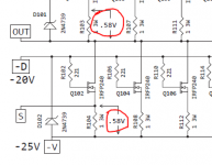
I should explain the process that led to the current operating stats of this amp. Several attempts were made to key on readings at various locations. The amp is essentially in two sections - 1. the front end (read pre) and 2. the output boards w/satellite bias PCB.
Each of those two section can/should be adjusted to it's optimum based on the designers specs with readings and targets at designated spots. That would include bias voltages across resistors on both sections. Difficulties arose when aiming for a particular bias value at the mosfet feed resistors. Several targets were suggested but never satisfactorily attained. If for example, something ~ 0.25A was set, the amp sounded weak and colorless. If adjustment on the front end were performed in an attempt to correct that condition the output bias values also changed.
Finally it was suggested to just set the front end to as close to optimum as possible (as described in the N. Pass design article) and ignore everything other than the DC offset at the terminals feeding the speakers. Doing that resulted in the most powerful, balanced and musical output from the build.
With some assistance/confirmation from Andrew , it was determined that NP had indeed specified 0.58V to all the output transistors in the single ended version of this amp. I didn't use matched mosfets and resistors on the OBs so the feed resistors all came in between 0.59 and 0.62.
So working backwards, keying in on zero DC at the outputs also brought the power draw spec in line with the designer's published estimate:
"The power transformer should be rated at 600 VA or more. Two channels of this amp will typically draw in excess of 300 watts, and we allow at least a 2 to 1 transformer margin."
Yes, that's a lot of energy, but remember the initial interest here was one of heat management in a reduced footprint. I chose the BA SE intentionally as it was reported to be a fire breather and presented the biggest challenge. The nearly distortion-free and powerful sound the build produces has come as an unexpected pleasant bonus.
A balanced version with a complementary output section is in the works. I hope to be able to use closely matched resistors and mosfets ($$$ - just bought a bunch of Lotto tickets) and I believe that build will allow more flexibility in bias settings to achieve higher efficiency and lower operating cost. It's anticipated that will also result in a smaller (slightly) footprint.
There's some progress on a new horizontal format also, so please stay tuned.......

Each of those two section can/should be adjusted to it's optimum based on the designers specs with readings and targets at designated spots. That would include bias voltages across resistors on both sections. Difficulties arose when aiming for a particular bias value at the mosfet feed resistors. Several targets were suggested but never satisfactorily attained. If for example, something ~ 0.25A was set, the amp sounded weak and colorless. If adjustment on the front end were performed in an attempt to correct that condition the output bias values also changed.
Finally it was suggested to just set the front end to as close to optimum as possible (as described in the N. Pass design article) and ignore everything other than the DC offset at the terminals feeding the speakers. Doing that resulted in the most powerful, balanced and musical output from the build.
With some assistance/confirmation from Andrew
, it was determined that NP had indeed specified 0.58V to all the output transistors in the single ended version of this amp. I didn't use matched mosfets and resistors on the OBs so the feed resistors all came in between 0.59 and 0.62.So working backwards, keying in on zero DC at the outputs also brought the power draw spec in line with the designer's published estimate:
"The power transformer should be rated at 600 VA or more. Two channels of this amp will typically draw in excess of 300 watts, and we allow at least a 2 to 1 transformer margin."
Yes, that's a lot of energy, but remember the initial interest here was one of heat management in a reduced footprint. I chose the BA SE intentionally as it was reported to be a fire breather and presented the biggest challenge. The nearly distortion-free and powerful sound the build produces has come as an unexpected pleasant bonus.
A balanced version with a complementary output section is in the works. I hope to be able to use closely matched resistors and mosfets ($$$ - just bought a bunch of Lotto tickets
) and I believe that build will allow more flexibility in bias settings to achieve higher efficiency and lower operating cost. It's anticipated that will also result in a smaller (slightly) footprint.There's some progress on a new horizontal format also, so please stay tuned.......
Attachments
Last edited:
- Status
- This old topic is closed. If you want to reopen this topic, contact a moderator using the "Report Post" button.
- Home
- Amplifiers
- Chip Amps
- Liquid Cooling Build