Bob, I was not mocking at you when I said you might want to try thermoelectric panels, they come in different sizes and shapes. But first as you have already suggested, is it a valid assumption to control the temperature, may be too much low is not an optimal performance and my idea is false, so how much low you want to go, we wait your results.
I didn't take you comment as anything other than genuine.")
I have a computer buddy who is constantly razzing me about when I'm going to start using the nitrogen. He says since it is non-conductive I should just immerse the whole thing and be done with it.
Haven't looked much at thermoelectric but I will.
I have a computer buddy who is constantly razzing me about when I'm going to start using the nitrogen. He says since it is non-conductive I should just immerse the whole thing and be done with it.
Haven't looked much at thermoelectric but I will.
Yes, with nitrogen you can over-clock it, and the only bottleneck is then the mechanical HDD  Any way, I wonder what results you will get when you start cooling this chip, can you do spectrum distortion measurements while you are maintaining the chip at a specific temperature?
Any way, I wonder what results you will get when you start cooling this chip, can you do spectrum distortion measurements while you are maintaining the chip at a specific temperature?The further away one can keep a protected/limited chipamp from triggering the protection, the better it will perform on typical dynamic range audio. The fewer clip incidents (that is both voltage clip and current clip) the better the audio performance.
Constant signal distortion measurements will not reveal this "triggering" if you avoid overloading the chip during the testing/measuring.
You are wasting your time doing THD at cool temperatures. It will not show any reduction in clipping incidents in a protected chipamp.
Based on the above a cooled chipamp should clip less often and less severely than a hot chipamp. This leads to my own conclusion. Always run the heatsink and chip as close to ambient temperature as possible for best audio performance.
Been watching this thread and hope to use Visual Analizer at some point with the Fremen Edition.
http://www.diyaudio.com/forums/software-tools/212908-exploring-visual-analyser-va.html#post3028849
http://www.diyaudio.com/forums/software-tools/212908-exploring-visual-analyser-va.html#post3028849
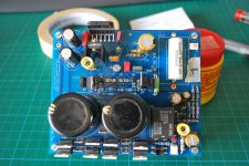
Hi guys, yesterday I've started with the build.
This morning I've tried to power on both channels but the relay don't started on both.
After a check-up i've found some bad join, now both relay and led are working after power on.
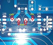
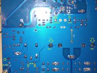
Unfortunately channel "1" has some problem, when I try to measure the DC offset I found 60mV and sometime the relay cut the circuit, in this situation the DC offset become 5V!
On C101/C102 I've +/-32.7V.
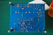
I've attached two pictures of this channel
The channel "2" has 10mV DC offset so I presume it's correctly working.
Thank a lot for any suggestion.
R.
This morning I've tried to power on both channels but the relay don't started on both.
After a check-up i've found some bad join, now both relay and led are working after power on.
Unfortunately channel "1" has some problem, when I try to measure the DC offset I found 60mV and sometime the relay cut the circuit, in this situation the DC offset become 5V!
On C101/C102 I've +/-32.7V.
I've attached two pictures of this channel
The channel "2" has 10mV DC offset so I presume it's correctly working.
Thank a lot for any suggestion.
R.
Attachments
Channel "1" has some problem, when I try to measure the DC offset I found 60mV and sometime the relay cut the circuit, in this situation the DC offset become 5V!
On C101/C102 I've +/-32.7V.
Hi Roberto,
please measure C102/C202:
IMHO the LM318 has to be replaced...
Attachments
A 30C (54F) rise for Tc is good. Not excellent.
But, is that actually Tc or is that the surface of the plastic packaging on the chip which could be at a very different temperature from the chipamp?
I would like to add an extra caution to Andrews caution above;-
I am not an expert, but measuring temperatures does fall under the category 'work' for me.
So-called 'laser' thermometers are quite inaccurate especially if measuring a small shiny surface.
The laser dot is not the same size as the field of view of the IR sensor which is actually reading the temperature. (especially up close since the laser and the IR sensor are some distance apart)
For a relatively accurate reading the target should be twice the size of the field of view of the IR sensor, and have an IR emmisivity of 0.95 for most hand held 'reasonably priced' thermometers.
Accuracy is sacrificed for convenience.
I'm Paused in my build, waiting for a couple of susumus which were missing from my Mouser order...
I think I bored myself with my post... must be time for bed...!
Bill
Last edited:
I've +14.55 on C102 and -14.22V on C202.Hi Roberto,
please measure C102/C202:
IMHO the LM318 has to be replaced...
I've a pair of 5W 8.2Ohm resistor, can I use they as load?
I've +14.55 on C102 and -14.22V on C202.
Fine, so your power supply is working as expected.
Most of the times the broken part is the LM318, I would swap it.
Hi Bill, You are correct. Andrew did a quite thorough explanation of the pitfalls of the laser temp tools that you confirm on another thread. Mine being a particular cheap model, I keep those limitations in mind. The only hedge against those problems I use is multiple shots at the same spot and an attempt to hold my hand at a uniform distance and position. I try to focus on the variation from a room temperature standard more than the value itself.
So far there have been few temperature related problems with the FE. Hopefully that will continue and there will not be a need for a more sophisticated temp monitoring device.
So far there have been few temperature related problems with the FE. Hopefully that will continue and there will not be a need for a more sophisticated temp monitoring device.
Roberto, this evening I'll take some measures on mine to give you a comparison.
If voltages are correct I see two possibilities:
- C32 has been overheated during soldering (try to measure it)
- LM318 is gone
Attachments
Thanks Dario, when led is on, the values are:If voltages are correct I see two possibilities:
- C32 has been overheated during soldering (try to measure it)
- LM318 is gone
- C101: 32.5V
- C201: -32.5V
- C102: -14.2V
- C202: 14.6V
- C14: 16.5V
- D4: 16.5V
so I think they are correct for my 22v toroid
About the solution, I can't measure capacitance of C32 ;(
For LM318 there are some test to do?
Someone know where I can get a single LM318?
Dario, can I get a new Ero C32 from you?
The other channel is now connect to the speaker and sound!
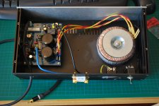
This is a picture of the "unlucky" channel with connection and case:
I've build a direct signal cable from board to preamp without rca plug in the middle
Roberto
Attachments
- Status
- This old topic is closed. If you want to reopen this topic, contact a moderator using the "Report Post" button.
- Home
- Amplifiers
- Chip Amps
- My_Ref Fremen Edition RC - Build thread