Another method - if you have two heat sinks - is applying automotive grinding compound on the surfaces and simply rubbing them together. Working through a couple grits will result in both parts being pretty close. You should be able to buy a couple small tubes of different grits from a local hardware or auto parts store. If you care to, this method will get you all the way to a mirror finish.
Last edited:
If you have similar heat sink and the surface looks the same, I would look for a gap at the top or bottom caused by an incorrect drilling angle for the screw. On the V1.2/3 boards the edge of the PCB prevented full contact of the chip. Dario made adjustments to hopefully prevent that, but if the LM3886 wasn't installed properly there may be an opening. Did you raise the LM3886 off the board before you soldered tha leads? Using a laser thermometer the 3886 and 317 are within 4 degrees ~ 78 - 81 F
Does your Lm317 CCS are running hot. I cant stay too much with my finger on them.
LM317s runs hot (54°C at 30° room temperature) but an heatsink it's not required, according datasheet.
It would not harm either to use one, the same code specified for R3 can be used.
While we are on the subject, If you are not using a part of the chassis as a heat sink, it is helpful to: 1. attach the standoffs you will be using. 2. Place a small shim/spacer under the heat sink before you locate the drill hole. That will allow clearance and a bit of "swing" on the heat sink that can compensate for improper alignment.
And again, use a spacer between the bottom of the LM3886 and the PCB. Dario noted earlier that he used a layout on the holes for that chip that are larger and as a result will let it drop to flush. Don't let that happen.
P.S. I'm assuming this is obvious but I will repeat it non the less. The attachment screw/bolt must be tight AS you solder the pins. Trusting you lineup measurements will probably cause difficulties later. A small dot of solder on the top of the boars at two locations will stabilize the chip enough to allow you to turn it over and complete the soldering on the bottom.
Last edited:
Now that the neighbors are up, after 30 minutes of loud pipe organ and big band jazz I'm getting 124 - 127 on the Lm3886 and 89 - 92 on the 317s. The room temp is 70 F.
I did discover that the outside corners of the heat sinks have a 10 degree spread between the two amps - so I need to do some work on my contact surfaces also.
I did discover that the outside corners of the heat sinks have a 10 degree spread between the two amps - so I need to do some work on my contact surfaces also.
O.T. Got a reply from Uriah and he is feeling much better and is making good progress in his situation. Let's keep him in our thoughts and prayers.
Yea, he's a good guy; I hope he beats this and gets well soon.
the temperature gradient along or across a conductor is determined by the rate of heat flow and the cross sectional area and the thermal resistance of the material.
Most of the heat flow of the metal heatsinking tab is across the thickness, i.e. from Tj to heatsink.
There is some heatflow from Tj near the middle of the chip to the big area formed by the tab backplate. But the thermal resistance and the area for conducting result in a lowish thermal gradient across the tab. If you could measure at different points on the tab you will find that they are at similar temperatures. This quite effectively confirms for you that the Tc of the device is within a couple of degrees of any of the tab, whether you measure the front face of the tab or the back face of the tab.
What I would not do is measure out at the corner of the tab farthest away from Tj.
But when looking at the plastic package the thermal gradients are very much different.
The thermal resistance is orders of magnitude higher and that gives rise to very large differences in temperature around different parts of the package. The surface of the package is generally much cooler than Tj and usually cooler than Tc. It is for this reason that I cannot see the logic in placing a temperature compensating device on top of a plastic packaged device. The thermal gradient completely defeats the accuracy of monitoring either Tj or Tc.
D.Self did experiments and published recommendations for how to locate the Vbe compensating device on the metal packaged To3 output device. Never try to extrapolate that to To247/To264/To3p devices.
Last edited:
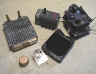
Well as you know, I'm all about what I hear. Since I have enough leftovers from a couple PC liquid cooling projects to build another rig, I am going to apply that same technique to a MyRef pair (probably the stock V1.2s). The pump has a wide range speed/flow adjustment that will allow everything from cool to almost no heat transfer at all.
I don't have too much of a concern about the amps stability as related to heat, but I dying to find out if I can hear a difference or notice a performance change at various settings. I will contact you directly when I get the system built.
I don't have too much of a concern about the amps stability as related to heat, but I dying to find out if I can hear a difference or notice a performance change at various settings. I will contact you directly when I get the system built.
Attachments
Last edited:
Are you sure you don't mind the noise caused by these machines (fans and pumps)? The LM3886 in very hot days here never went hot on average listening levels, it was warm. I did use small heatsinks for LM317s as I did not want to follow the datasheets, TBO.
What is the story behind keeping the ICs super cool Then you can use thermoelectric cooling, I am sure it is a silent colleague
Next step, I want to wind my own transformers, I read too much about it, and learnt how to correctly do it, it will take sometime before I finish two transformers.
What is the story behind keeping the ICs super cool
Then you can use thermoelectric cooling, I am sure it is a silent colleague Next step, I want to wind my own transformers, I read too much about it, and learnt how to correctly do it, it will take sometime before I finish two transformers.
Metal, I cheated a bit and you caught me. What is shown in the pic is well oversized and will only be used for the base experiment, That stuff is on a 120 cm fan base/standard. If there is a sensible advantage everything would be downsized possibly all the way to 60 cm. I have built some coolers that can't be heard 3 feet away. Wont know if it's even worth the effort till I play around a bit. These pumps are virtually silent.
And no, even though I know how to use it, I'm not going to try liquid nitrogen.
Ok Andrew - Talk to me This is 82 db at 12 feet
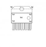
Ta Temperature Ambient
Tc Case Temperature
Tj Junction Temperature
And no, even though I know how to use it, I'm not going to try liquid nitrogen.
Ok Andrew - Talk to me
This is 82 db at 12 feetTa Temperature Ambient
Tc Case Temperature
Tj Junction Temperature
Attachments
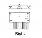
Those temps on the tabs are good guides to the TC of the chip.
These are quite low @ 111°F to 115°F.
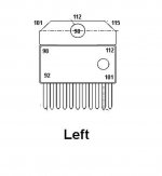
The markings on the left diagram are wrong.
The TC are plastic case surface temperatures. They have no close relationship to Tc.
The Tj are tab temperatures. Thes are close to Tc, certainly not Tj which is the junction temperature of the chip, buried way inside the device.
These are quite low @ 111°F to 115°F.
The markings on the left diagram are wrong.
The TC are plastic case surface temperatures. They have no close relationship to Tc.
The Tj are tab temperatures. Thes are close to Tc, certainly not Tj which is the junction temperature of the chip, buried way inside the device.
certainly not Tj which is the junction temperature of the chip, buried way inside the device.
So there is actually no way to measure Tj without a formula, correct? And I would assume the self-protection is looking at Tj also?
Last edited:
Hi Bob,
there is another way for "silent" cooling of the chips. You can combine two alu-extruded heatsinks so that the fins are "looking" towards each other.
For example this one and another one rotated 180°.
The two gaps on the outer side can be sealed with adhesive tape. On one of the short sides you mount the cooler. The other short side leads straight out of the case. You get the idea looking at the picture below
Just an idea.
Greets
Sven
there is another way for "silent" cooling of the chips. You can combine two alu-extruded heatsinks so that the fins are "looking" towards each other.
For example this one and another one rotated 180°.
An externally hosted image should be here but it was not working when we last tested it.
The two gaps on the outer side can be sealed with adhesive tape. On one of the short sides you mount the cooler. The other short side leads straight out of the case. You get the idea looking at the picture below
An externally hosted image should be here but it was not working when we last tested it.
Just an idea.
Greets
Sven
Thanks Andrew.
metal - I didn't comment on part of your question. Theoretically and as suggested by the data sheet, there should be a temperature or small range where the chip operates at optimal performance. I'm just curious to see if that can be both controlled and if it is detectable by ear.
bK - That looks effective, but for my experiment I need something that is not passive as in the sentence above.
Last edited:
- Status
- This old topic is closed. If you want to reopen this topic, contact a moderator using the "Report Post" button.
- Home
- Amplifiers
- Chip Amps
- My_Ref Fremen Edition RC - Build thread