I have a trafo from a sharp subwoofer amp (using a stk412-400) that I would like to repurpose for a chipamp.
It has 5 cables in the mains and 7 in the secondaries.
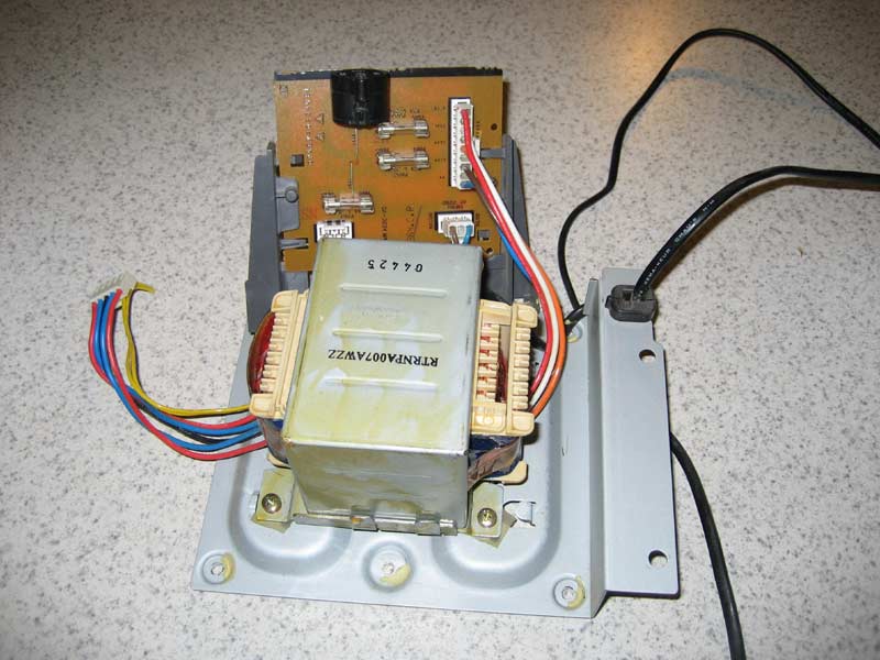
Mains: Blue, brown, orange, white and red.
Secondaries: 2xred, 2xblue, black and 2xyellow.
The amp has a board with a rotary voltage selector (110v, 127v, 220v and 230-240v) and fuses. The power cable is 2 pronged with no ground.
In the secondaries, if I measure red-blue=21V. Blue-black=21v and red-black=42. The yellows are together and measure 15v (all this idle).
I tried goggling the number stamped in it and was unable to find anything useful.
Do you think it could be used?
It has 5 cables in the mains and 7 in the secondaries.
Mains: Blue, brown, orange, white and red.
Secondaries: 2xred, 2xblue, black and 2xyellow.
The amp has a board with a rotary voltage selector (110v, 127v, 220v and 230-240v) and fuses. The power cable is 2 pronged with no ground.
In the secondaries, if I measure red-blue=21V. Blue-black=21v and red-black=42. The yellows are together and measure 15v (all this idle).
I tried goggling the number stamped in it and was unable to find anything useful.
Do you think it could be used?
Attachments

The voltages from it should match the one you need for your chip amp.
I have several trafo's waiting for their chip amps, and several chip amps waiting for their trafo ... I have 3-4 amps I am still hoping will come back to life, onkyo 555, teac ag-v890, pioneer vsx1020 to name a few ... and I need something like a 29 0 -29 trafo for a lm 3886 based amp, and I just located the right trafo that I have liberated from a combo box system ...
I want to stuff the chip amp inside the teac chassis, not get the trafo out, cos that thing only has a bad power amp, the tuner, the whole rest of it works great including the remote ...
I have a few more, I cant remmeber it all ... all I can say is ... a 30 0 -30 v 300VA capacity whether you pull it from an amp or buy it from the store are about the same. Yea toroidal isn't the same as EI isn't the same as bobbin core etc etc, but for a power transformer it doesn't matter a whole lot as long as its decent quality and your pic looks very good, fuses for each output line and what not ... similar to what I would be using I'd say.
Anyway Just my opinion, wait til la few more people post. I am not an electrical tech, just a man with a soldering iron and a dream.
Cool.
Srinath.
I did include that in the first post:Check your voltages using black as your reference ie blue black, red black, on either side of black, I suspect that black may be your centre tap. If so it may certainly be useful.
Red-blue=21v
Blue-black=21v
Red-black=42v
Well, I checked/disassembled the voltage selector (4 pos rotary switch) and when you select 110v it uses the mains blue and brown. The path includes a 4A 250v fuse.
I'll test with the bulb and see if I get confirmation
I have a trafo that is center tapped on the input side as well (obviously due to the 220/110v deal), its not used on that trafo in the amp it was in, but I have weird needs now, so I may try to use it backwards ... Let me see what it looks like when I try it backwards.
Cool.
Srinath.
Cool.
Srinath.
Last edited:
Well, I tested for continuity on the secondaries and any pair I select (red to blue, black to red or black to blue) rings.
(By "rings", I assume that you mean that the meter makes an audible tone, when there is continuity, instead of meaning that there is a damped oscillation being seen on an oscilloscope display.)
That should be OK, if it's one big winding with an actual center tap, instead of two separate secondaries, which is what it must be if there are only three wires for the secondary.
Try measuring the resistance (Ω) between each pair. The resistance should correspond with the length of the wire being measured.
There should be two pairs with lower resistances and one with a higher resistance. The wire color that is in both of those pairs with the lower resistances should be the center tap. The pair with the one higher resistance of the three should not include the center tap, since the higher reading should be from one end of the secondary to the other end, and should be about double the other two measured resistances, in this case.
(If the resistances are extemely low values, then remember to short the probe tips together, to measure the instrinsic resistance, and then subtract that from your measurements.)
Last edited:
Looks like it.
I had forgotten that you had 2x of some of the colors. Sorry.
To complete the picture, you should probably also refer to blue1 and blue2, instead of just "blue", in your post above.
So if you could, please also give measurements labeled as blue1 to red1, blue1 to red2, blue2 to red1, and blue2 to red2.
Did you short your probe tips together and measure that resistance, and then subtract that from each of your resistance measurements? (Also, check them shorted together, again, afterward, and if it's changed, re-do the measurements. Or, keep checking it until it stops changing, before starting the measurements, but then check it afterward, anyway.)
The reason I ask is because if black is the center, and black to each red is 0.7 Ohms, then red to red should be 1.4 Ohms, not 1.2. And blue to blue would be 1.0, not 0.7, since black to any blue is 0.5.
So it LOOKS like either we're wrong about how they are configured, or, the measurments are not accurate.
Or maybe I'm missing something, or looking at it wrong. But, enlarging your photo, I noticed that the secondary's PCB connector also has the wires in order, symmetrically, as red, blue, black, blue, red, which is the same order that we seem to be guessing that the taps are in.
Shorted leads: 0.3
Resistance with leads subtracted:
red1 to blue1: 0.2
red1 to black: 0.4
red1 to blue2: 0.7
red1 to red2: 0.9
blue1 to black: 0.2
blue1 to blue2: 0.4
blue1 to red2: 0.7
black to any blue: 0.2
black to any red: 0.4
blue2 to red2: 0.2
My meter only has 1 decimal, so it looks like the guess is right.
Blue to black 0.2 and blue to blue 0.4
Red to black 0.4 and red to red 0.9 (if my meter had 2 decimals, this could be confirmed).
What do you think?
If u have pulled it from a subwoofer, the components on the pcb that was powered by it, tell the specs of the transformer, better than anyone can guess. Your transformer is rated to drive the stk power amp u mentioned in the first post. Just refer the data for the stk and that will give u an idea of the power rating of the transformer (high current windings).
The smaller voltages were used for the low pass filter circuits, most probably designed around op-amps(may be discrete also).
Gajanan Phadte
The smaller voltages were used for the low pass filter circuits, most probably designed around op-amps(may be discrete also).
Gajanan Phadte
Last edited:
Silver.
You must find which tappings are NOT connected to other tappings.
This allows you to label each winding and identify how many tappings are on each winding. A winding MUST have at least two tappings. A centre tapped winding MUST have at least three tappings.
First: find out how many windings you have.
Second: label the separate windings.
Silver.
You must find which tappings are NOT connected to other tappings.
This allows you to label each winding and identify how many tappings are on each winding. A winding MUST have at least two tappings. A centre tapped winding MUST have at least three tappings.
First: find out how many windings you have.
Second: label the separate windings.
Andrew, the transformer has 7 wires in the secondaries. They are separated in 2 bundles (separate connectors):
5 wires: red-blue-black-blue-red All of these seem to be the same winding (they all have continuity).
2 wires: yellow-yellow These are a separate winding.
 I'm assuming that if they have continuity, they are part of the same winding, if that is incorrect, please let me know.
I can't tell you if they are the same winding. Only you can do that test.
Similarly for the primary or primaries.
You have to find which wires are connected and which groups do not connect to any other group.
You must do this FIRST !!!
I'm using "groups" instead of windings. Does that help?
Similarly for the primary or primaries.
You have to find which wires are connected and which groups do not connect to any other group.
You must do this FIRST !!!
I'm using "groups" instead of windings. Does that help?
Now I'm confused, I "learned" a long time ago that if the wires have continuity are part of the same winding (please let me know if this is incorrect).
Based on this premise I tested for continuity the secondaries and primary.
Found that there is only 1 primary winding (all 5 wires have continuity).
There are 2 secondaries:
The red-blue-black-blue-red bundle is a single winding (all 5 wires have continuity).
The yellow-yellow pair is a separate winding (yellow-yellow have continuity, they have no continuity to other wire(s)).
Again, this is based on the premise that if they have continuity, they are part of the same winding. Is this premise incorrect?
Good.
Now go back and re-read you measuring results. You should be able to see which bits of a winding are connected in what order from one end to the other.
My uneducated guess is:
red1-2 are the beginning-end of the winding
black is the center
blue1-2 are somewhere midpoint between a red and the black
- Status
- This old topic is closed. If you want to reopen this topic, contact a moderator using the "Report Post" button.
- Home
- Amplifiers
- Chip Amps
- Another "can I use this transformer?" thread