An alternative use for the TDA7293 (and TDA7294) is a very low power amplifier with peerless imaging and resolution. It can be done like: Set the gain to the datasheet minimum and then get the power voltage low enough to support that. The result is extraordinary audio performance at the cost of ineffective output power. Also, the heatsink requirement is almost gone (because low power use).
I did this on purpose for little table radios and computer speakers.
In those cases, it is known that the speaker won't require a lot of power.
Switchable flea power mode. . .
Dual Primaries transformers can easily be switched between full or half voltage with a dpdt switch ("manual class g") or automated with a relay. So, the actual problem is finding a lovely way to switch the feedback resistor (for lower gain) on the amplifier to access its highest resolution (for when it is used at half voltage).
TDA7293's inbuilt voltage amplifier is capable of doing two very different audio tasks, both of which are excellent--grandpa's hifi -or- party blaster (although the in-between results in "neither"). So, we don't need two different amplifiers, IF we could somehow arrange switchable feedback resistor value.
Any ideas how to do that last step?
Little Brothers!
These are for the single chip boards.
Some notes:
The smallest dual-sided board works much better than a big board.
The bootstrap cap value is range 33uF~47uF on the solo board (or twice as much for the parallel board).
The feedback resistor value is in the range of 25k~27k; and the input load resistor value is in the range of 22k~25k
The gain has to be fine tuned for best stability behavior, so do go ahead and buy the multi-turn cermet trimmer.
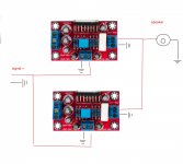
Hi-Fi version (note the voltage and gain), 45W
suggested transformers include 20-0-20vac and 22+22vac
(If even lower voltage is used, you can dial the gain lower too.)
or
Party amp version (note the voltage and gain), 70W
relevant transformers include 25-0-25vac and 28+28vac
These are for the single chip boards.
Some notes:
The smallest dual-sided board works much better than a big board.
The bootstrap cap value is range 33uF~47uF on the solo board (or twice as much for the parallel board).
The feedback resistor value is in the range of 25k~27k; and the input load resistor value is in the range of 22k~25k
The gain has to be fine tuned for best stability behavior, so do go ahead and buy the multi-turn cermet trimmer.
Hi-Fi version (note the voltage and gain), 45W
suggested transformers include 20-0-20vac and 22+22vac
(If even lower voltage is used, you can dial the gain lower too.)
or
Party amp version (note the voltage and gain), 70W
relevant transformers include 25-0-25vac and 28+28vac
I have attached them.No images here.
Note the power voltage and gain differences.
Attachments
Modular Parallel amp has several differences, but here's the one to watch out for:
Multiply the bootstrap cap value times the number of chips.
For example,
33uF or 47uF for one chip
68uF or 100uF for 2 chip parallel amp
100uF or 150uF for 3 chip parallel amp
With the TDA7293 solo (one) chip boards, also double-check to make sure it uses pin6 and pin12 for bootstrap cap connection.
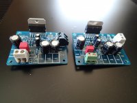
I do have lot of this PCB and both TDA 7293 and TDA 7294 IC: Kit TDA7294 Dual Channels Audio Power Amplifier Board 60W 60W DC ±25V ±38V | eBay
According to “danielwritebac” recommendation this changes has been done: Powercaps 220uF. To obtain a 26dB gain: 220uF with 2k7 fs and 68k fb. From pin 6 to pin 14: 100uF. Power will be 2x34v DC.
Since I do have so many IC and PCB I wonder to go for another TDA7293 in BTL or as slave. The changes I have done don’t influence on the possibility to BTL or slave modus, I hope??
From the store that sold me PCB I have drawings how to connect two TDA7293 in BTL modus, except there is no place on “my” PCB for the 22 k resistors that can be seen on TDA7293 called “A” on the drawings. But I have come into doubt about BTL, reading about input impedance problems unless a bridging unit is used. Other “drawbacks are that in bridge modus loadspeaker impedance should not be lower than 8 ohm. My 2x34V DC power might not suit BTL modus?? Comment and advice about this is welcome.
So far I have not found anything here on diyAudio how to connect two of “my” PCB in a slave modus. A drawing would be of very good help.
Bridging is relevant for subwoofer amplifiers:
16 ohm subwoofer = two TDA7293 chips (simple bridge)
12 ohm subwoofer = two TDA7293 chips (simple bridge)
8 ohm subwoofer = four TDA7293 chips (parallel then bridge)
6 ohm subwoofer = four TDA7293 chips (parallel then bridge)
4 ohm subwoofer = six TDA7293 chips (triple-parallel then bridge)
3 ohm subwoofer = eight TDA7293 chips (quad-parallel then bridge)
Bridging will give approximately a 3x boost, at the cost of more power supply loading, less efficiency and halved quality at the tweeters (treble quality is not a great concern with subwoofer amplifiers).
Double check the limiter action by multiplying the number of chips by 45 to estimate how much low-bass the subwoofer amplifier can produce without signal modification of the inbuilt limiter. That estimate also helps durability.
A coarse estimate for power: With the efficiency down to 50% due to the cost of bridging, then half of your power supply current will be spent to warm the heatsink, and the other half will be used to move the woofer cone. SO, on that 4 ohm example with 6 chips, 270W capacity, you'd need at least 10% more than 270*2 = VA. Roughly estimated, 600VA transformer is bare minimum.
Compare the above power estimate, with a Class D amplifier, bridged so that the efficiency falls to 75%, so that a quarter of the power supply ends up warming the heatsink and 3/4ths of the power supply is used for moving speaker cones. As you can see, a less expensive transformer will do, perhaps the one you already own.
Compare the above two power estimates with a solo TDA7293 driving one 8 ohm woofer or a parallel TDA7293 driving two 8 ohm woofers: If the gain is set high enough for amplifier placidity, even while driving the speaker, the efficiency nears 70%. To make up the difference in power output, you'd need a woofer 4.5db more efficient. . . and then you didn't need to bridge. This example where the not-bridged amplifier has the more efficient woofer, has the lowest power supply costs of all, and the highest fidelity. Opinion: Buying a more efficient woofer probably costs less than the amplifier equipment for driving normal woofers.
Thanks for your answer, danielwritesback.
Your message about BTL was very "clear". The TDA7293 I am building is ment for a ordinary stereo amplifier, not a subwoofer. So the idea of BTL is, thanks to your clear explaination,is now "dead".
But what about the slave modus. Can this be recommended(good for low impedance)??
And how should this be realized with those PCB I have?
Eivind S
While 34V into 4R is possible, it would require a large heatsink. According to the Datasheet, the dissipation is about 28 watts at full power into 4R. The same voltage into 8R dissipates about 12 watts. As the master/slave or as ST call it Modular mode, the two output stages are fooled into believing they are each feeding 8R. So the lower 12W per chip (24W total) is dissipated in two separate places.
In modular mode, the heatsink could be smaller or the Amp would run much cooler with the same size heatsink.
In modular mode, the heatsink could be smaller or the Amp would run much cooler with the same size heatsink.
Last edited:
TDA7293 datasheet's "Modular" schematic shows the hookups. The two chips need to be situated very near to each other to keep the loop areas small.While 34V into 4R is possible, it would require a large heatsink. According to the Datasheet, the dissipation is about 28 watts at full power into 4R. The same voltage into 8R dissipates about 12 watts. As the master/slave or as ST call it Modular mode, the two output stages are fooled into believing they are each feeding 8R. So the lower 12W per chip (24W total) is dissipated in two separate places. In modular mode, the heatsink could be smaller . . .
There's a lot of hookups so that you might rather purchase the purpose-made parallel board (featured at post#1, this same thread).
34vdc unregulated rails are likely to go down to near 30vdc under load (involving 4 ohm speakers), thus there's not much challenge to one TDA7293, (and 4W doesn't make a big different to heatsink size) except. . .
At much less than full bast, such as more normal listening levels, the parallel TDA7293 amp will probably run more efficiently than single-chip TDA7293 amp (this comment made assuming the speaker is connected).
TDA7293 datasheet's "Modular" schematic shows the hookups. The two chips need to be situated very near to each other to keep the loop areas small.
There's a lot of hookups so that you might rather purchase the purpose-made parallel board (featured at post#1, this same thread).
34vdc unregulated rails are likely to go down to near 30vdc under load (involving 4 ohm speakers), thus there's not much challenge to one TDA7293, (and 4W doesn't make a big different to heatsink size) except. . .
At much less than full bast, such as more normal listening levels, the parallel TDA7293 amp will probably run more efficiently than single-chip TDA7293 amp (this comment made assuming the speaker is connected).
Yes my assumption was a regulated 34V rail, I don't know why as I I always use unregulated rails. All you other points are correct although as the saying goes, there is no such think as a heatsink that is too large,
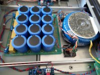
I bought a made in China 2 channel amp board with TDA7293 at ebay very low price some years past. It comes with 2 4700µ elkos and bridge rectifier . I have 2*22V transformer and an additional power on module that operates on 12 volts remotely . So far so good but the sonic quality is a bit disappointing in mid and high frequency. What is the present state-of-the art chip amp?
If you have followed whats written on the PCB, I can understand your disappointments. If you use the component value that danieldwritesback have recommended, I think you will be satisfied.
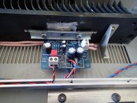
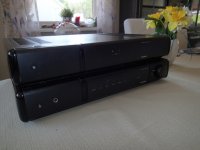
I used TDA7293 in a Tandberg 4036 cabinet. The original poweramplifier could not be "saved". The result was suprisingly good.
Eivind S
I used TDA7293 in a Tandberg 4036 cabinet. The original poweramplifier could not be "saved". The result was suprisingly good.
Eivind S
Attachments
- Home
- Amplifiers
- Chip Amps
- TDA7293 Parallel kit from ebay (modular/slave style, no lossy emitter resistors)