Hi Andrew, Your clairvoyant. Those are the same questions I was thinking about asking as you made your post. The longest lead will be from the outer-most MyRef to the JC-2 and it is twisted. I've been wondering how much I would gain by carrying that through everywhere. The Neotech OCC is really stiff but I could make it so the "Y" is equidistant between the signal and ground tabs on the MyRefs.
The other question I was considering (now we are in the weeds) is how important is to have the same type of wire in both the signal out and the ground/return. Iv'e seen several DIY interconnect designs that use different sizes and metals.
The other question I was considering (now we are in the weeds) is how important is to have the same type of wire in both the signal out and the ground/return. Iv'e seen several DIY interconnect designs that use different sizes and metals.
I asked the gurus at Parts Connexion and Sonicraft for their recommendation and they both said 20 awg for connecting the boards and 14 awg to signal out posts. I bought a bunch of silver plated stranded copper from ApexJr in 20 and 16 to play with also. It will be fun to see if I can hear any differences.
Here's a pic of one experiment. Braided silver 30ga - have same in copper but waiting for some flex Teflon tuning to arrive.

Here's a pic of one experiment. Braided silver 30ga - have same in copper but waiting for some flex Teflon tuning to arrive.
Some good progress to report.
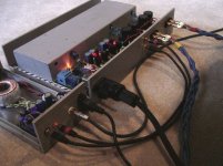
All components are mounted and fully functional. I tried to use twists where possible but wires are short. Placed the furthermost MyRef feed under the other one and shortened the output leads to the posts.

I mounted pins on the LighterNote, a screw terminal on the JC-2 and each of the signal "Ins" on the MyRefs.
Note: 90 degree angle on LN signal in.

Here's how the cat-6 cable attaches to the LN and runs under both the JC-2 and the transformer can.

....and the other end.


I didn't do as much "wire sound" testing as had been planned. Everything other than the red out to posts is ApexJr silver plated teflon stranded copper. I did notice some "over brightness" with the solid silver interconnects.
All components are mounted and fully functional. I tried to use twists where possible but wires are short. Placed the furthermost MyRef feed under the other one and shortened the output leads to the posts.
I mounted pins on the LighterNote, a screw terminal on the JC-2 and each of the signal "Ins" on the MyRefs.
Note: 90 degree angle on LN signal in.
Here's how the cat-6 cable attaches to the LN and runs under both the JC-2 and the transformer can.
....and the other end.
I didn't do as much "wire sound" testing as had been planned. Everything other than the red out to posts is ApexJr silver plated teflon stranded copper. I did notice some "over brightness" with the solid silver interconnects.
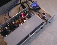
Here's the latest on the music server. Will probably shorten power cable to 2.5" HD. That is for system (OS) files only as an external USB box will hold all the media.


The base of the DAC chassis ended up being a separate unit. I might combine them later to avoid an external link. Just got the kit for this DAC yesterday and have not started to populate. It's the Dario Inserra favorite I mentioned earlier

Temporarilly using a Lexicon Omega on a 16' coax from my HT receiver to feed it and the integrated, Sounds fantastic!

I see a ventilation challenge coming forth that will probably dictate more separation than I had originally thought. I bought a pair of 70mm low noise fans but haven't figured out how I will use them yet.


The white card shows the size of the other DAC that's still being worked on. The transformer has dual voltages that will power either unit.

Please excuse the fuzzy pictures. Not on my best game this morning")
...and yes, I'm getting tired of looking at dirty grey primer.
The base of the DAC chassis ended up being a separate unit. I might combine them later to avoid an external link. Just got the kit for this DAC yesterday and have not started to populate. It's the Dario Inserra favorite I mentioned earlier
Temporarilly using a Lexicon Omega on a 16' coax from my HT receiver to feed it and the integrated, Sounds fantastic!
I see a ventilation challenge coming forth that will probably dictate more separation than I had originally thought. I bought a pair of 70mm low noise fans but haven't figured out how I will use them yet.
The white card shows the size of the other DAC that's still being worked on. The transformer has dual voltages that will power either unit.
Please excuse the fuzzy pictures. Not on my best game this morning
...and yes, I'm getting tired of looking at dirty grey primer.
Last edited:
I will check in on the DAC thread to get the latest and greatest trani. I bought the one shown to power the WM8740 unit several months ago but will upgrade to R-Core a bit later.
I was referring to a discrete shunt regulator for the analog part...
I bet you can guess which one I'm referring to...
DAC ADDED
After another struggle with some more silly mistakes (see saga starting here: http://www.diyaudio.com/forums/digital-source/186245-dac-2496-ak4393-dac-kit-cs8416-ak4393-5532-a-139.html#post2955962)
I got the Mini 2496 DAC assembled and operating. Most everything is mounted with double sided foam tape for now. Several mods and additions have to be made before optimum sound and perminent placement is achieved. Will trim transformer wires, move power LED to front and get two switches that match a bit later.
How does it sound - FANTASTIC. Please see the thread above to read all the raves. Unbelievable sound quality from a small piece of equipment.
Attachments
That's some nice looking work. I like the idea of the cover for the transformers; no EMF or RF sneaking into things.
Does it work in practice ? Is there an audible difference with the shield removed ? Also, how close can transformers be to each other before trouble starts ? Can toroids stack ?
Does it work in practice ? Is there an audible difference with the shield removed ? Also, how close can transformers be to each other before trouble starts ? Can toroids stack ?
Getting Excited Now!
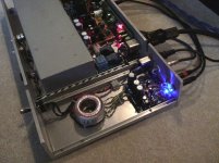
Thanks squalor, The propose of the metal can was to minimize interference between the amp and the computer above it, not so much for a transformer to MyRef problem. I have seen transformers as close as 1/2 inch from the boards and no problems were reported. Maybe others will give some advice.
Shows "Stack" with monitor, mouse and KB. More on that later.....

White doughnuts are antennas for the media server .It has full hub and router capabilities on-board.


Wires, cables and cords - we got plenty. I'll trim/build everything for final setup.

All three modules will have individual metal covers, and I hope some pretty paint and accents in the near future.

Thanks squalor, The propose of the metal can was to minimize interference between the amp and the computer above it, not so much for a transformer to MyRef problem. I have seen transformers as close as 1/2 inch from the boards and no problems were reported. Maybe others will give some advice.
Shows "Stack" with monitor, mouse and KB. More on that later.....
White doughnuts are antennas for the media server .It has full hub and router capabilities on-board.
Wires, cables and cords - we got plenty. I'll trim/build everything for final setup.
All three modules will have individual metal covers, and I hope some pretty paint and accents in the near future.
Last edited:
Here's the fun part.
I'm using JRiver Media Center on the computer. I allows remote control from phone apps - in this case one called "GIZMO".
Here it is on a Samgung GSII.

With "load media server with windows" active, log in screen disabled and the JR application in the start-up folder, the server sits listening. One can have as many servers on as many boxes as they require.

Phone finds server and authenticates with credentials supplied by the main app.
Media type selection screen appears.

Pick one...

Play will cycle through album, playlist or directory.

Interface provides full control and the rocker on the phone controls the volume.

Now if that doesn't beat your grandfathers RCA Victrola - nothing does. Look Ma - NO mouse and keyboard!!!
One final element to implement is a "WOL" or "wake on lan" function. I downloaded an Android app that will on/off the computer from the phone.
WHEEEEWWW!!!
I'm using JRiver Media Center on the computer. I allows remote control from phone apps - in this case one called "GIZMO".
Here it is on a Samgung GSII.
With "load media server with windows" active, log in screen disabled and the JR application in the start-up folder, the server sits listening. One can have as many servers on as many boxes as they require.
Phone finds server and authenticates with credentials supplied by the main app.
Media type selection screen appears.
Pick one...
Play will cycle through album, playlist or directory.
Interface provides full control and the rocker on the phone controls the volume.
Now if that doesn't beat your grandfathers RCA Victrola - nothing does. Look Ma - NO mouse and keyboard!!!
One final element to implement is a "WOL" or "wake on lan" function. I downloaded an Android app that will on/off the computer from the phone.
WHEEEEWWW!!!
Last edited:
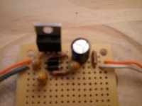
Today I'm trying to build a regulator using LM338 on blank circuit board .
I have some noobie questions and need some help. First question. The attached jpg calls the three legs of LM338 IN , COM and OUT. I'm assuming IN corresponds to the Pin 1 dot on the 338 case ? Is it so ?
Second question. Where does the pot go ?
I'm going to copy/paste what Regi22 said in Mauro's big thread:
Mouser BoM for 5V regulator
R1: 71-RN55D-F-100
R2: 71-RN55D3300F
R3: 71-RN55D-F-499
C1, C3: 80-T356B105K050AT
C2: 80-T350G106K035AT
C4: 667-EEU-FC1V101
D1, D2: 512-1N4002
Pot: 313-2420F-100K
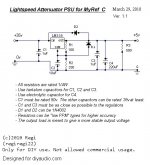
We will tap the +35vdc from the already rectified and smoothed out from the My_RefC PSU. You can hook up a pair of wires to the solder side of the big 10.000uF caps, this is a clear/easy place to solder. These will give us around +35vdc, so we will step it down to +5vdc using an LM338 regulator. We could use the lower-current-rated LM317, but Uriah told me that LM338 is more stable, so no place for discussion with the small price difference they have. You can mount this circuit on a little piece of stripboard or veroboard. You can even mount it point-to-point if you have enough care.
Here are some technical explanations, not necessary to succesfully build the circuit:
-An output load resistor makes any regulator happier It keeps a constant load all the time, which turns out to give a better steady voltage. The LM338 datasheet says that it has a minimum load current ranging from 3.5 to 10mA, so a 500 Ohm resistor will suck 10mA. Plus the Lightspeed consumption, it will be enought current. R3 is using 50mW, so a 1/4W resistor will suffice.
-R1 is 100 Ohm to allow pass a 12.5mA adjustment pin current. Everywhere is recommended to put there at least 10mA. With 1.25v it consumes 15mW, so an 1/4W resistor is enough.
-R2 is 330 Ohm. I don't know how to calcule its consumption, but I know that you need a 1/2W resistor if you go above 1.6k having R1=100. SO we are fine with a 1/4W resistor.
...you could use the same value as R2 for R3. Should be perfect, even a bit better than 500 Ohm. 330Ohm will consume 75mW
-C1 and C3 are bypass caps, which improves regulator performance. C2 improves ripple rejection. C4 is there to provide some output capacitance and doing a bit of post-filtering, like C3. They have to be tantalum types (or even film types) because of its high-frecuency response.
The only one cap that needs to be 50v is C1. 35v would work, but too tight for long-term endurance. The others can be anything above 5v or 10v.
-D1 and D2 provide protection in case that the currents from capacitors return back and damage the regulator. 1N4002 or 1N4003 are enough.
-Uriah suggested me to use resistors with a low PPM. That means to have a low thermal drift. Output voltage will fluctuate less due thermal variations. But, in practice, with a more or less steady power consumption, this is not a big deal.
-I would go with metal film resistors because of its advantages, but it goes down to personal choice. For the load resistor R3, it is suitable to use something between 200 and 500 ohms aprox. The lower, the more consumption, and maybe the better regulation. 500 Ohms will consume 50mW (10mA), 200 will consume 125mW (25mA). For D1 and D2, you can use RS part nº 628-8953 (1N4002). There isn't any advantage in using 1N4003 (maximum 200v), as 1N4001 already support max 100v.
This circuit will provide you a first-class regulated +5vdc supply for your Lightspeed or anything else you want. You can even hook up a LED to ensure that it keeps working. The regulator will get a bit hot because of the big voltage drop, but not too much because of Lightspeed's low current consumption. You will have to attach it to an small heatsink, or to the same heatsink as the LM3886, but making sure that it's well insulated from it.
Building the Lightspeed attenuator with Uriah's matched LDRs should be trouble-free. It should take no more than a square inch veroboard. But with the supplied kits, boards are included. Hook it up to the regulated PSU and you're done. The PSU shouldn't take up more than an square inch board.
So I guess you turn the pot while measuring the +5V line after R3 but why did he spec a 2 gang pot and where does it go in the circuit ?
I have some noobie questions and need some help. First question. The attached jpg calls the three legs of LM338 IN , COM and OUT. I'm assuming IN corresponds to the Pin 1 dot on the 338 case ? Is it so ?
Second question. Where does the pot go ?
I'm going to copy/paste what Regi22 said in Mauro's big thread:
Mouser BoM for 5V regulator
R1: 71-RN55D-F-100
R2: 71-RN55D3300F
R3: 71-RN55D-F-499
C1, C3: 80-T356B105K050AT
C2: 80-T350G106K035AT
C4: 667-EEU-FC1V101
D1, D2: 512-1N4002
Pot: 313-2420F-100K
We will tap the +35vdc from the already rectified and smoothed out from the My_RefC PSU. You can hook up a pair of wires to the solder side of the big 10.000uF caps, this is a clear/easy place to solder. These will give us around +35vdc, so we will step it down to +5vdc using an LM338 regulator. We could use the lower-current-rated LM317, but Uriah told me that LM338 is more stable, so no place for discussion with the small price difference they have. You can mount this circuit on a little piece of stripboard or veroboard. You can even mount it point-to-point if you have enough care.
Here are some technical explanations, not necessary to succesfully build the circuit:
-An output load resistor makes any regulator happier It keeps a constant load all the time, which turns out to give a better steady voltage. The LM338 datasheet says that it has a minimum load current ranging from 3.5 to 10mA, so a 500 Ohm resistor will suck 10mA. Plus the Lightspeed consumption, it will be enought current. R3 is using 50mW, so a 1/4W resistor will suffice.
-R1 is 100 Ohm to allow pass a 12.5mA adjustment pin current. Everywhere is recommended to put there at least 10mA. With 1.25v it consumes 15mW, so an 1/4W resistor is enough.
-R2 is 330 Ohm. I don't know how to calcule its consumption, but I know that you need a 1/2W resistor if you go above 1.6k having R1=100. SO we are fine with a 1/4W resistor.
...you could use the same value as R2 for R3. Should be perfect, even a bit better than 500 Ohm. 330Ohm will consume 75mW
-C1 and C3 are bypass caps, which improves regulator performance. C2 improves ripple rejection. C4 is there to provide some output capacitance and doing a bit of post-filtering, like C3. They have to be tantalum types (or even film types) because of its high-frecuency response.
The only one cap that needs to be 50v is C1. 35v would work, but too tight for long-term endurance. The others can be anything above 5v or 10v.
-D1 and D2 provide protection in case that the currents from capacitors return back and damage the regulator. 1N4002 or 1N4003 are enough.
-Uriah suggested me to use resistors with a low PPM. That means to have a low thermal drift. Output voltage will fluctuate less due thermal variations. But, in practice, with a more or less steady power consumption, this is not a big deal.
-I would go with metal film resistors because of its advantages, but it goes down to personal choice. For the load resistor R3, it is suitable to use something between 200 and 500 ohms aprox. The lower, the more consumption, and maybe the better regulation. 500 Ohms will consume 50mW (10mA), 200 will consume 125mW (25mA). For D1 and D2, you can use RS part nº 628-8953 (1N4002). There isn't any advantage in using 1N4003 (maximum 200v), as 1N4001 already support max 100v.
This circuit will provide you a first-class regulated +5vdc supply for your Lightspeed or anything else you want. You can even hook up a LED to ensure that it keeps working. The regulator will get a bit hot because of the big voltage drop, but not too much because of Lightspeed's low current consumption. You will have to attach it to an small heatsink, or to the same heatsink as the LM3886, but making sure that it's well insulated from it.
Building the Lightspeed attenuator with Uriah's matched LDRs should be trouble-free. It should take no more than a square inch veroboard. But with the supplied kits, boards are included. Hook it up to the regulated PSU and you're done. The PSU shouldn't take up more than an square inch board.
So I guess you turn the pot while measuring the +5V line after R3 but why did he spec a 2 gang pot and where does it go in the circuit ?
Attachments
Why 338 ? During the discussion it was thought that LM338 would be more stable. Regiregi22 agree's with you and said in the discussion, "Mouser doesn't have the L338 in their stock, you could replace it with the LM317 without a hassle. It provides already more than 20x times the requiered power by the Lightspeed,and is as good as the LM338. Here is the part number: 512-LM317T I'm a novice builder and do not understand these things. I've completed the circuit and attached pics.
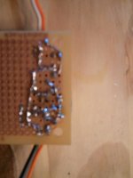
Below the LM338 is the 100R, the D2 (in4001), the D1 and the 330R . The underside is messy, especially at the C2-R1-R2-D1 junction. I have not powered the circuit yet.
Andrew, are you saying the pot is not needed and the +5V is achieved with resistor values ?
Below the LM338 is the 100R, the D2 (in4001), the D1 and the 330R . The underside is messy, especially at the C2-R1-R2-D1 junction. I have not powered the circuit yet.
Andrew, are you saying the pot is not needed and the +5V is achieved with resistor values ?
Attachments
I like you build Squalor, it looks pretty similar to my original one
Regarding IC regulator choice, Andrew is right, there is almost no difference in using an LM317 or an LM338, apart from the LM338 huge current performance which is useless in this application, btw. An LM317 should be more economic to implement.
You're right again Andrew, regarding the 330ohm resistor chosen, it will give about 5.3vdc, a more precise approach should be 300ohm wich gives you those wanted 5vdc. And once again, the 500ohm resistor at the output is not needed at all, it already has a ~430ohm load by design.
Squalor, regarding the pot selection, it is part of the Lightspeed design, not of the regulator itself. If you built it as shown, it will just give a regulated voltage. Now you have to attacht it to some LDRs with a dual gang pot in order to control their resistance by changing the voltage supplied.
You don't use the pot to change the regulator voltage (which, btw, could be another interesting approach), instead, the regulator always supply those +5vdc, and a pot after that forms a voltage divider that forces more or less current through the LEDs inside the Silonex devices (thus changing the LDR resistance).
Are you using the regulator for that end (Lightspeed volume control) or another thing?
regiregi22 said:I like you build Squalor, it looks pretty similar to my original one
Regarding IC regulator choice, Andrew is right
Regi, I'm so glad you could reply. You spoke of this circuit at post 514 of Uriahs Ultimate BOM GB thread , years ago. I also remember Uriah suggesting to you to add caps at the input to keep the LDR powered while the amp turns off. I don't remember the value.
Andrew usually is right. I think that bothers some people but I always try to study his posts and feel kinda honored that he replied to one of my posts.
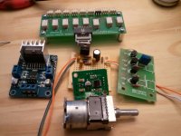
As seen in the attached pic, I'm almost done with the LDR. The long board w/ the relays is a Darwin from TPear. The blue board is a stepper motor controller. The tiny board atop the RegiReg is a Sure IR receiver. The first thing I want to power is a Alps powered 100K log pot.
This is the first time I built without a printed circuit. I hoped someone could comment on the pic of my solder joints but realize now the pic is too grainy. I will remove 499R and try to post a clearer pic.
Attachments
- Status
- This old topic is closed. If you want to reopen this topic, contact a moderator using the "Report Post" button.
- Home
- Amplifiers
- Chip Amps
- MyRef Integrated Solutions