Mike,
I have some more questions about your interesting circuit, specifically on the most recent version:
1. What amount of attenuation is obtained with the 25kOhm potentiometer on the input?
2. Do you recommend any particular pot on the input? Audio (log) or linear taper? What about constructing a stepped attenuator? Any suggestions for that?
3. What is the input impedance on the most recent version with the 25kOhm pot and the 20k input resistor on the opamp? What would it be if I wanted to use a 10kOhm resistor on the opamp input to give 2X gain?
4. I notice you again changed the opamps, this time to the LME49860. Any particular reason for that? Are they stable in this circuit, and did you bypass the power supply pins in the same way as with your previous versions?
5. Is this circuit now in use in your system? If so, how do you like it?
The more I look at your circuit, the more I believe it would provide the basis for an excellent preamp for my system. Thanks for your continued attention to my questions.
Last edited:
Hi majerjack,
That's a lot of good questions there. But I've had a long stressful day, and it's getting late, so sometime tomorrow I'll do a write up for you. If you haven't done so already, I recommend reading through the entire thread, and also take a look at the Rane tech pub I posted the link for on "Accelerated Slope Tone Controls" since I've incorporated that into the current version, it's a really informative read.
MIke
Hi majerjack, I'm back as promised.
1. What amount of attenuation is obtained with the 25kOhm potentiometer on the input?
A) With the input level control set to maximum it will be about (-.75dB), and of course, at minimum it fully attenuates.
2. Do you recommend any particular pot on the input? Audio (log) or linear taper? What about constructing a stepped attenuator? Any suggestions for that?
A) The input level controls are there to eliminate the differences in output levels of the signal sources so that when one switches from one source to another there will be no aparent change in loudness, they aren't intended to be used as volume controls. So you could use linear or log taper pots here, I used linear trim pots, it really isn't critical at all.
3. What is the input impedance on the most recent version with the 25kOhm pot and the 20k input resistor on the opamp? What would it be if I wanted to use a 10kOhm resistor on the opamp input to give 2X gain?
A) The input impedance with a 20kOhm resistor in the circuit as shown is 12kOhm, with 10kOhm it's 8kOhm. Input impedance would be 5.1kOhm if a 4.99kOhm were used for 4X gain, any decent signal source should work just fine with that.
4. I notice you again changed the opamps, this time to the LME49860. Any particular reason for that? Are they stable in this circuit, and did you bypass the power supply pins in the same way as with your previous versions?
A) For my initial version, I just used parts I had on hand. At the time I had a bunch of OPA2132's in the parts bin, so that's what got used. I built the first one on a piece of perf board, and used a bunch of cheap slide switches instead of rotary switches because that was what I had on hand for testing. When I was satisfied that it worked as expected, I ordered all new parts to build it "for real" using LM4562's, tighter tolerance caps and resistors, and good quality rotary switches. And yeah, the power supply bypass configuration shown is what I used in all versions, which is not to say that further improvements couldn't be realized with further experimenting, but it shows no issues on the O'scope as is. The latest version of TI Tina 9 has the LME49860 included, the earlier Tina 7 that I used didn't have any of the LM4562 family available.
5. Is this circuit now in use in your system? If so, how do you like it?
A) Unfortunatly, I've not had the time or money to actually build the latest version due to ongoing employment issues, but the intermediate version I built that had +/- 11dB adjustment range and the accelerated slope filters sounds good, and is mostly noise free. I eventually will get back to it and put the latest version together and post the results, and I might be willing to make PC boards available if there's enough interest.
Mike
Last edited:
Would purchase a PCB
I would be interested in purchasing a PCB, if it used LM4562, and had space and extra holes to allow for choices in different sized capacitors, resistors, and did not use any SM components.
I eventually will get back to it and put the latest version together and post the results, and I might be willing to make PC boards available if there's enough interest.
Mike
I would be interested in purchasing a PCB, if it used LM4562, and had space and extra holes to allow for choices in different sized capacitors, resistors, and did not use any SM components.
Hi Davy,
Sorry it took so long to reply, I was pleasantly surprized to see this thread come back to life agian.
I'm not reallty into the whole "botique parts" thing, so any good quality components from known to be reputable suppliers is what I generally recommend using. Any decent polypropylene or mylar type film cap is just fine here as long as it has a high enough working voltage, say 25 volts or higher for a minimum, and should be the tightest tolerance you can find, no more than +/- 5% (I buy a lot of 2% to 3% tolerance caps from DigiKey).
As for supply voltage, the usual regulated +/- 15 volt source will work fine here.
Attched are the schematics for the current version of the tone circuit and an appropriate regulated power supply.
I recommend using either an OPA2132 type Opamp like in the early version, or even better, use one of the LM4582/LME49710 types as in my current version. Those chips have better than average specs, are relatively forgiving of less than perfect circuit layouts, and better than average output drive capability that this circuit needs.
View attachment 367653
View attachment 367654
Mike
I tried to make the this circuit. I'm using the one-sided copper plate. Is there significant errors? Is there a grounding issue? sorry for my english.
Attachments
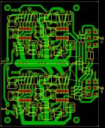
I tried to make the this circuit. I'm using the one-sided copper plate. Is there significant errors? Is there a grounding issue? sorry for my english.
Hi attalostesla,
Sorry for taking so long to reply, there's been a lot of "bad juju" cramping my style the past few years, so I haven't been able to indulge in the fun side of life for a while.
Anyhoo...I was wondering if you ever built that tone control I designed? If so, how's it been working for you? Did you make the PCB you designed? Any performance issues? Just wondering.
Mike
I have done some informal research (farting around with prototype boards) and I have come to realize that the primary reason most tone controls sound so bad is because people use their tone controls to compensate for baffle step. And the Bandaxall tone controls usually have a turnover frequency of 1000 Hz, which is way too high; and the slope is all wrong too. So you're boosting frequencies that don't need boosting; and these frequencies happen to be in the range that our ears are most sensitive to. Hence, you get muddy mid-bass, which most people are used to but to me it sounds bad.
Most popular size bookshelf speakers have a baffle step between 200 to 500 Hz; larger floor standing speakers are of course lower. So a bass control with a turnover frequency around 250 Hz is just about right.
I built a hard wired equalizer for my shop speakers. I did it empirically, and I ended up with a shelving equalizer with turnover frequencies of 200 and 500 Hz, with 6 dB total boost. I did not realize it at the time, but this is a classic baffle step compensation circuit. My shop speakers are suspended from the ceiling, which of course exacerbates the baffle step.
After realizing this, I measured the frequency response of my computer sound system, which consists of an old tabletop "hi-fi" mini system. This system has full sounding bass in spite of its size, although the "bass" is really just kind of boomy. The speakers are tiny but remarkably powerful. Anyway, when the "tone" setting was set to "optimum" it was nothing more than baffle step compensation.
So my next preamp will have a variable baffle step compensation circuit with several turnover frequencies. I have a lot of research to do before I commit to it, but I'm confident that I will come up with a winning combination.
A few preamps from the good old days had selectable turnover frequencies for the tone controls. I have emulated this with excellent results.
Why don't manufacturers incorporate some of these features into their consumer grade products? I guess it's because their target demographic is just lazy and ignorant. You would think that by now we would have some really great equipment available, but a trip to the store yields only cheap junk peddled by know nothing salesmen. I've been on the hi-fi scene since the early 70s, and at that time I was confident and hopeful that the hobby would grow into something really awesome. But the opposite has happened; with Ipads and ridiculously tiny speakers ad nauseum it's gone in the opposite direction. I think consumers are used to terrible sound; look at the popularity of the Bose "acoustimass" system, which is the "gold standard" for many consumers. Yuck!
Last edited:
I use my tone control for slight treble lift
I do not use my tone control for bass enhancement or attenuation. I use the treble control for small controlled boost to compensate somewhat for my natural reduction in highs (I am almost 60).
I think most oldster audiophiles - if they can get past the anti-tone control bias of their youth, would embrace small treble boost, esp if the turnover point were adjustable and the treble was a shelving type (this is important).
Unless I am missing something after browsing thru this thread, the tone control offered up by Doug Self meets your needs.
Here is what the frequency plot looks like. Note that both the gain and shelving frequency are adjustable.

This is not what I would call a shelving response. A shelving response would rise and then flatten out to a horizontal line until the natural roll-off at the upper end of the response of the circuit. So, for the very low boosts of 1-5 db at a 6 db this would result in a very small set of frequencies in which there is rise in response, followed by a wide range of frequencies where the boost is constant. Sorry, but I cannot diagram this except as follows:
_________________ 3 db
/_________________ 2 db
/_________________ 1 db
/__________________ flat
Well ...
'Shelving response' was the phrase that popped into my head when I posted the message. Doug Self describes it as a 'variable frequency tone control'. In any case his latest version is on page 141 of the #5 edition of Linear Audio bookzine. I invite you to take a look at the circuit. I've built it. It improves upon traditional tone controls inline with the reasons given in this thread.
'Shelving response' was the phrase that popped into my head when I posted the message. Doug Self describes it as a 'variable frequency tone control'. In any case his latest version is on page 141 of the #5 edition of Linear Audio bookzine. I invite you to take a look at the circuit. I've built it. It improves upon traditional tone controls inline with the reasons given in this thread.
Well ...
'Shelving response' was the phrase that popped into my head when I posted the message. Doug Self describes it as a 'variable frequency tone control'. In any case his latest version is on page 141 of the #5 edition of Linear Audio bookzine. I invite you to take a look at the circuit. I've built it. It improves upon traditional tone controls inline with the reasons given in this thread.
The capability of the filter, to change the turnover frequencies for both the bass and treble response, is great.
I will see how much it is to purchase the Doug Self document. I hope that someone would design and sell a PCB, however.
The capability of the filter, to change the turnover frequencies for both the bass and treble response, is great.
I will see how much it is to purchase the Doug Self document. I hope that someone would design and sell a PCB, however.
Well, I've got one. However it has never been fabbed and tested. I built my test project that drove me to craft this on vero board. The PCB measures 144mm deep by 220mm wide.

I designed a 4 section Baxandall circuit back in 1983, for a preamp I was building, and I love it. I've built the same thing several times since in other projects, and consider it about perfect.
It's my opinion that room acoustics will usually throw off the tone balance more than cheap pots like I use (I buy Alphas, and then measure them, and select the good ones - probably about 20% of them are further off than I'm comfortable with). But I feel that I get much better flexibility and end result by having 4 sections; Low, Mid-Low, Mid-Hi and Hi. Two sections just isn't enough IMO.
Never had any stability issues. Put 100 ohm R's at the output of each opamp circuit (outside of the feedback loop) for better stability, unless there's already an R before any capacitive loading, and of coarse good power supply bypass caps within an inch of any opamp (0.1uF or so).
Last edited:

Well, I've got one. However it has never been fabbed and tested. I built my test project that drove me to craft this on vero board. The PCB measures 144mm deep by 220mm wide.
An externally hosted image should be here but it was not working when we last tested it.
If you ever end up making boards, I will buy enough for a stereo unit. I appreciate the fact that you used connectors to allow easy connection of pots, inputs, outputs, PS voltages and ground. My only suggestion might be to add local ceramic bypasses to allow COG or X7R 2-4uf bypasses, per Tom Christiansen's recommendations on the Neurochrome website (he posts here in the vendor's section for his Mod 86 amp board).
... My only suggestion might be to add local ceramic bypasses to allow COG or X7R 2-4uf bypasses, per Tom Christiansen's recommendations on the Neurochrome website (he posts here in the vendor's section for his Mod 86 amp board).
The board is setup to take WIMA poly bypass caps. That's what those rectangular parts are at either end of every opamp.
The board is setup to take WIMA poly bypass caps. That's what those rectangular parts are at either end of every opamp.
Great! Excellent. When can I buy this?
Would you be willing to post the art here?
- Home
- Amplifiers
- Chip Amps
- A usable tone control