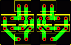
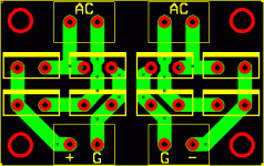
Ehm... probably not...
Dear Darkmoebius,
thanks for the kind words, I'm sure you exaggerated a bit.
Moreover, I really have no intention of selling boards. If you look inside the zip files (I mean the ones named gcXX.zip), you may find both the ExpressPcb source that you may edit at will (even adding a tube buffer!) and a pdf of the pcb, suitable for "printing" the pcb on a copper board.
Why don't you try modifying the pcb on your own? Using ExpressPcb is VERY easy. This is not the place for discussing this topic; if you need help with the program, feel free to email me.
Etching a pcb is not too difficult, too. You have first to transfer a printout of the pcb to the copper board and then to plunge the board for a while in a solution of ferric chloride. Transferring is the difficult part; you may use a special paper (I heard someone got happy with this product: http://www.techniks.com/) or to use a plain overhead transparency as a "negative" for a photoresist-coated board. You don't even need a special UV lamp: a cheap "solar" lamp may do the job. There's a great tutorial about that, but - sorry - it is in italian:
http://www.vincenzov.net/tutorial/stampati/stampati.htm
If you look at the pictures you might get some idea of the whole process.
Hope this helps,
Massimo
Dear Darkmoebius,
thanks for the kind words, I'm sure you exaggerated a bit.
I'm very sorry, but my experiments with GC are at the very beginning. I plan to build two power amps, maybe to experiment some combination of components and maybe maybe to build an integrated amp, redesigning the pcb to allow easily soldering a stereo pot. I have no near-future plan for adding a tube buffer. Did you check with Joe Rasmussen if a pcb is available from him?If you ever get the urge to do Joe R's tube-buffered IGC on a pcb, I'd love to buy some.
Moreover, I really have no intention of selling boards. If you look inside the zip files (I mean the ones named gcXX.zip), you may find both the ExpressPcb source that you may edit at will (even adding a tube buffer!) and a pdf of the pcb, suitable for "printing" the pcb on a copper board.
Why don't you try modifying the pcb on your own? Using ExpressPcb is VERY easy. This is not the place for discussing this topic; if you need help with the program, feel free to email me.
Etching a pcb is not too difficult, too. You have first to transfer a printout of the pcb to the copper board and then to plunge the board for a while in a solution of ferric chloride. Transferring is the difficult part; you may use a special paper (I heard someone got happy with this product: http://www.techniks.com/) or to use a plain overhead transparency as a "negative" for a photoresist-coated board. You don't even need a special UV lamp: a cheap "solar" lamp may do the job. There's a great tutorial about that, but - sorry - it is in italian:
http://www.vincenzov.net/tutorial/stampati/stampati.htm
If you look at the pictures you might get some idea of the whole process.
Hope this helps,
Massimo
Yeah, Yeah, Yeah.........
......... I thought it was something like that.........
Very nice. I am working on a single bridge using the Avondale PCB, 860s, some small heatsinks and a blue LED as my first step towards building my first project (a mono IGC). Among other things of course, like the KWAK clock, DACKit, AmpKit pcbs I now have awaiting stuffing - and a 637 / 634 pre amp.
Ah well....... DIY Audio is the thief of time, ...{complete witty phrase here}...!
Cheers
Jon
......... I thought it was something like that.........
Very nice. I am working on a single bridge using the Avondale PCB, 860s, some small heatsinks and a blue LED as my first step towards building my first project (a mono IGC). Among other things of course, like the KWAK clock, DACKit, AmpKit pcbs I now have awaiting stuffing - and a 637 / 634 pre amp.
Ah well....... DIY Audio is the thief of time, ...{complete witty phrase here}...!
Cheers

Jon
Don't forget that you can parallel your trace on the other side of the board for nothing if you order from ExpressPCB You have to be careful where you put your "text" on their boards since it shows up as copper on the finished product.peranders said:
100 mil traces can cope with more than 4 ampere!
Hey Antomas!!!
You're right!! That ExpressPCB software is incredibly easy to use(so far).
I was able to use your schematic as a starting point and convert it to Joe Rasmussen's tube-buffered IGC in an hour, which included learning how to create "new components" (mainly the 6922 dual-triode).
I haven't gotten to the PCB part yeat, but that I'll gt to that tonight. I guess the hardest part of the learning curve will be allowing enough room for the actual component sizes.
Thanks for the suggestion, now I've got another way to spend my nights not sleeping
You're right!! That ExpressPCB software is incredibly easy to use(so far).

I was able to use your schematic as a starting point and convert it to Joe Rasmussen's tube-buffered IGC in an hour, which included learning how to create "new components" (mainly the 6922 dual-triode).
I haven't gotten to the PCB part yeat, but that I'll gt to that tonight. I guess the hardest part of the learning curve will be allowing enough room for the actual component sizes.
Thanks for the suggestion, now I've got another way to spend my nights not sleeping

Guys, have you seen my rectifier bridge for MUR860, or any TO220 diode.
http://www.diyaudio.com/forums/showthread.php?s=&threadid=19725&highlight=mur860
http://www.diyaudio.com/forums/showthread.php?s=&threadid=19725&highlight=mur860
Re: ...you won...
Oh yes!!
Ciao
Lorenzo
antomas said:...an ExpressPcb file!
Ciao,
Massimo
P.S. Battipaglia? The city famous for the wonderful cheese and the good tube amps?
Oh yes!!

Ciao
Lorenzo
Hi Jackinnj,
Thanks for pointing that out. I used only the bottom layer to help the "press-and-peel" guys.
Traces and text should share the same encoding: yellow->silkscreen, red->top copper layer, green->bottom copper layer. Did you noticed anything in the wrong place?
Ciao,
Massimo
Don't forget that you can parallel your trace on the other side of the board for nothing if you order from ExpressPC
Thanks for pointing that out. I used only the bottom layer to help the "press-and-peel" guys.
You have to be careful where you put your "text" on their boards since it shows up as copper on the finished product.
Traces and text should share the same encoding: yellow->silkscreen, red->top copper layer, green->bottom copper layer. Did you noticed anything in the wrong place?
Ciao,
Massimo
Attachments
Hi darkmoebius,

Ciao (please sleep at night)
Massimo
I'm very happy with that! You're a fast worker!I was able to use your schematic as a starting point and convert it to Joe Rasmussen's tube-buffered IGC in an hour, which included learning how to create "new components" (mainly the 6922 dual-triode).
This is indeed a good way to make your wife/fiancee/partner happy...now I've got another way to spend my nights not sleeping

Ciao (please sleep at night)
Massimo
Chapeau!
Hi Peranders,
I noticed those very-high-specs PHE450 capacitors. Are they only good for decoupling or for coupling as well? You are certainly a Rifa caps heavy user and expert: what do you suggest for coupling?
Thanks very much for your very valuable answer.
Massimo
Hi Peranders,
Compliments for this beautiful piece of engineering!Guys, have you seen my rectifier bridge for MUR860, or any TO220 diode.
I noticed those very-high-specs PHE450 capacitors. Are they only good for decoupling or for coupling as well? You are certainly a Rifa caps heavy user and expert: what do you suggest for coupling?
Thanks very much for your very valuable answer.
Massimo
Doesn't matter?
Hi Darkmoebius,
do you mean that I used a custom component in ExpressSch (not ExpressPcb)? If so, just look at the two: wouldn't you really like to draw a Gainclone schematics with a squared LM3875? If the problem is instead in ExpressPcb
  just let me know.
Massimo
P.S. I warned all the PcbGainCloners to check if their components fit on a paper printed pcb before etching it...
P.P.S. I'd like to send you a private mail but your address is disabled.
Hi Darkmoebius,
do you mean that I used a custom component in ExpressSch (not ExpressPcb)? If so, just look at the two: wouldn't you really like to draw a Gainclone schematics with a squared LM3875?
 If the problem is instead in ExpressPcb
 Massimo
P.S. I warned all the PcbGainCloners to check if their components fit on a paper printed pcb before etching it...

P.P.S. I'd like to send you a private mail but your address is disabled.
Resistor variation #1
Hi everybody,
following some discussion with Zldz (thanks Lorenzo!!!) I made two new versions of the pcb. The first version allows mounting as output resistor (see picture):
1. A .2 ohm Caddock resistor on the component side (like in the previous version).
2. A .7 uH inductor on the component side (the yellow line), plus a Caddock 10 ohm resistor on the copper side. Mounting details are below.
3. Since the current flowing into the 10 ohm resistor should be low, would it be resonable using a small-power resistors (say .5W) in place of the Caddock? Let's try and blast it.
Mounting details:
Inductor: 12 turns of 0.9 mm wire (or AWG19) on a 8 mm cilinder. Inductor length 11 mm. Inductance should be 0,75uH.
Copper-side mounting of the Caddock resistor: solder and hot glue the resistor with the copper side facing the insulated side of resistor to avoid shorts. Maybe both sides are insulated. Who knows...
Massimo
Hi everybody,
following some discussion with Zldz (thanks Lorenzo!!!) I made two new versions of the pcb. The first version allows mounting as output resistor (see picture):
1. A .2 ohm Caddock resistor on the component side (like in the previous version).
2. A .7 uH inductor on the component side (the yellow line), plus a Caddock 10 ohm resistor on the copper side. Mounting details are below.
3. Since the current flowing into the 10 ohm resistor should be low, would it be resonable using a small-power resistors (say .5W) in place of the Caddock? Let's try and blast it.

Mounting details:
Inductor: 12 turns of 0.9 mm wire (or AWG19) on a 8 mm cilinder. Inductor length 11 mm. Inductance should be 0,75uH.
Copper-side mounting of the Caddock resistor: solder and hot glue the resistor with the copper side facing the insulated side of resistor to avoid shorts. Maybe both sides are insulated. Who knows...
Massimo
- Status
- This old topic is closed. If you want to reopen this topic, contact a moderator using the "Report Post" button.
- Home
- Amplifiers
- Chip Amps
- Yet another GC pcb...


