I burnt a TDA7293 while testing it on a universal PCB. Reading through this thread, I thought I can make a reasonable guess about what went wrong from the symptoms. I don't have an oscilloscope, so I have limited information.
1. I powered it, shorted inputs and connected no load. Output DC offset was near zero. Multimeter didn't show any AC voltage.
2. I connected a 1kOhm load. Something went wrong here. Chip was a little warm. At this load I guess it should stay cool.
3. Then connected my desktop and played a 1kHz sine wave using ARTA.
3. Something went wrong after a while and I saw a bright flame come through the chip and burning smell as well.
4. I disconnected immediately.
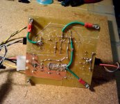
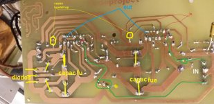
I was surprised to see liquid, probably oil coming out of the chip. Do amplifier chips contain oil for cooling? This photo shows oily spots on the chip.
1. I powered it, shorted inputs and connected no load. Output DC offset was near zero. Multimeter didn't show any AC voltage.
2. I connected a 1kOhm load. Something went wrong here. Chip was a little warm. At this load I guess it should stay cool.
3. Then connected my desktop and played a 1kHz sine wave using ARTA.
3. Something went wrong after a while and I saw a bright flame come through the chip and burning smell as well.
4. I disconnected immediately.
I was surprised to see liquid, probably oil coming out of the chip. Do amplifier chips contain oil for cooling? This photo shows oily spots on the chip.
An externally hosted image should be here but it was not working when we last tested it.
Thanks. That's what I also felt. I had used all components according to TDA7293's datasheet. No load was connected! I think since I wasn't using a designed PCB, I must have shorted some pins or gotten a dry solder. That caused oscillations.
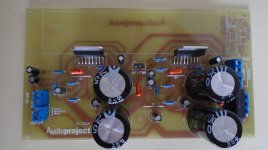
Anyways, now I plan to use a proper designed PCB.
Anyways, now I plan to use a proper designed PCB.
I suspect the amp oscillated disastrously.
What schematic did you use?
Did all of National's "optional" components get fitted, as recommended by dozens of Forum Members?
This has been an amazingly insightful thread.
Sometime back I found some old TDA2615 samples our company had gotten way back when. I pulled up the datasheet and it looked like a fun project so off I went. This is my first amp project, so I drew up the schematics based on the reference design, but didnt give much thought to the PCB layout. We have a QuickCircuit 5000 (The Scratcher we call it) that I used to scratch out the PCB.
Stuffed the board Thursday evening, verified pinouts, and made sure there were no shorts that would result in a chip meltdown like murah experienced. Those are never any fun.
I applied power, and it worked right off the bat, except for... The Hum/Buzz/Noise thing. +
I suspected the PCB may be the problem and came across this thread while looking for answers. I had managed to introduce almost every potential problem brought up here.
Ground loops? Check. Rectifier on board? Check. Insufficient filtering? Check. Insufficient traces? Check. I had pretty much made the poster child for bad PCB layout.
I initially tried the 200nF decouplers soldered directly to the chips pins hoping for the magic bullet cure (I had 2200uF electrolytics on there already), but no joy. So I cut out all the ground traces, connected the supply ground to the top copper of the board, and then branched dedicated ground wires from there to the IO etc.
That eliminated almost all the noise. I was delightfully stunned. There is still a very slight hiss, but it is a 95% improvement.
Im going to try some of the cap combos suggested to see if I can tweak it further, but I am quite pleased, and wanted to thank all of you for sharing your knowledge.
Hello, by the way. Ive been lurking through the forum for awhile, but this is my first post.
Many thanks!
Sometime back I found some old TDA2615 samples our company had gotten way back when. I pulled up the datasheet and it looked like a fun project so off I went. This is my first amp project, so I drew up the schematics based on the reference design, but didnt give much thought to the PCB layout. We have a QuickCircuit 5000 (The Scratcher we call it) that I used to scratch out the PCB.
Stuffed the board Thursday evening, verified pinouts, and made sure there were no shorts that would result in a chip meltdown like murah experienced. Those are never any fun.
I applied power, and it worked right off the bat, except for... The Hum/Buzz/Noise thing.
+ I suspected the PCB may be the problem and came across this thread while looking for answers. I had managed to introduce almost every potential problem brought up here.
Ground loops? Check. Rectifier on board? Check. Insufficient filtering? Check. Insufficient traces? Check. I had pretty much made the poster child for bad PCB layout.
I initially tried the 200nF decouplers soldered directly to the chips pins hoping for the magic bullet cure (I had 2200uF electrolytics on there already), but no joy. So I cut out all the ground traces, connected the supply ground to the top copper of the board, and then branched dedicated ground wires from there to the IO etc.
That eliminated almost all the noise. I was delightfully stunned. There is still a very slight hiss, but it is a 95% improvement.
Im going to try some of the cap combos suggested to see if I can tweak it further, but I am quite pleased, and wanted to thank all of you for sharing your knowledge.
Hello, by the way. Ive been lurking through the forum for awhile, but this is my first post.
Many thanks!
skiz,
Welcome!
That's a great story. It perfectly illustrates how critical the grounding scheme usually is, and proves how significant the effects can be, with a real-world example.
Thanks for sharing that!
Sounds like you did great work on implementing the fix, too.
Regards,
Tom Gootee
Welcome!
That's a great story. It perfectly illustrates how critical the grounding scheme usually is, and proves how significant the effects can be, with a real-world example.
Thanks for sharing that!
Sounds like you did great work on implementing the fix, too.
Regards,
Tom Gootee
Last edited:
It was an eye opener for me.
I knew that PCB layout could effect performance of a circuit, and had read somewhere that audio amps could be particularly touchy about it, but this was such a simple circuit I didn't really think it would be a game changer, especially for my purposes. And the PCB was just so darn good-looking fresh off the scratcher......
It was a nasty buzz, and the chip was heating up quick as was described here as well. It couldnt be as simple as grounding scheme, this was a "real" problem. I spent a while going over the board verifying the layout and looking for shorts left by the QuickCircuit, bad solder joints, etc.
Implementing the fix was pretty down and dirty. My once shiny board looks like the Frankenstein monster now. Having found the problem I can re-scratch the board and refine a few things in the process, and I learned a good bit from this exercise. Im going to finish this amp up, and move on to a more powerful amp, still based around an IC. Moving forward I would like to build something discrete.
So many project ideas, so little time.....
I knew that PCB layout could effect performance of a circuit, and had read somewhere that audio amps could be particularly touchy about it, but this was such a simple circuit I didn't really think it would be a game changer, especially for my purposes. And the PCB was just so darn good-looking fresh off the scratcher......
It was a nasty buzz, and the chip was heating up quick as was described here as well. It couldnt be as simple as grounding scheme, this was a "real" problem. I spent a while going over the board verifying the layout and looking for shorts left by the QuickCircuit, bad solder joints, etc.
Implementing the fix was pretty down and dirty. My once shiny board looks like the Frankenstein monster now.
Having found the problem I can re-scratch the board and refine a few things in the process, and I learned a good bit from this exercise. Im going to finish this amp up, and move on to a more powerful amp, still based around an IC. Moving forward I would like to build something discrete.So many project ideas, so little time.....
Attachments
- Status
- This old topic is closed. If you want to reopen this topic, contact a moderator using the "Report Post" button.
- Home
- Amplifiers
- Chip Amps
- Hum on TDA7294