janneman said:Hi Mark,
Yes I was referring to the error you get when trying to get linear-in-dB range with binary steps. But your curves are not that bad. What about using one extra relay to switch the 22ok between two values? You could use the 18-32dB range of the 4 bit thing, which is pretty linear, and use the extra relay to say shunt the 220k with a resistor to lower the gain by 18dB, bringing your linear range to full 32dB. Does that make sense? It would mean you need some logic because you no longer have a nice binary count. Or maybe you do have if the extra step is made 16dB.
Jan Didden.
Ah - "monotonic" means constant rising steps as the input rises (eg 00111111 must give a lower voltage than 01000000). It doesn't mean constant step-size. This is why I was confused when you said it wouldn't work before - I knew that it would be monotonic, but wasn't sure about step size...
The more I think about this scheme, the more I like it. If you wanted a less "purist" implementation, CMOS switches could be used around the virtual earth... I'll be trying this soon.
Cheers,
Mark
Hi
I am pleased to read this thread, as we have been producing a preamplifier with a 64 step relay / SMD resistor attenuator for years. It works great, and has very good linearity (<0.5dB).
We don't use the circuit proposed by Mr. Hennesey, as it does not give us the desired linearity.
However in our Sidewinder preamp, we use a combination of ladder and feedback attenuation (to optimize for noise performance). You can download the user manual with schematics of this attenuator and preamp here:
http://www.lcaudio.dk/sidewind.PDF [3.5 Mb]
Maybe not perfect graphic quality, but i think you can get the principle of this ultra high performance pre-amp.
All the best from Denmark
Equal sized steps (linearity?) ends up adding too much complexity.
The biggest advantage is a useful balance control function, but lots of people don't seem to need this so I don't think it is worth it. We don't need a huge number of steps either. Remember the chip amp credo: Not one more part that is necesary.


The biggest advantage is a useful balance control function, but lots of people don't seem to need this so I don't think it is worth it. We don't need a huge number of steps either. Remember the chip amp credo: Not one more part that is necesary.
LC Audio said:http://www.lcaudio.dk/sidewind.PDF [3.5 Mb]
Maybe not perfect graphic quality, but i think you can get the principle of this ultra high performance pre-amp.
It's hard to see what you are doing because of the quality of the image - could you post a better quality image?
So I might be wrong, but it looks rather like you might be using cascaded constant impedance attenuators. If this is the case then I'm glad - I tried to make the case for them in this post
Variac said:Mark H,
I like the simplicity of your calcs. After all, if we want "everything plus the kitchen sink" we should just get Apox's.
Thanks
Variac said:I'd really appreciate a schematic that is totally clear, very simple, with parts values so even a gainclone guy could build it!
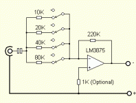
Here it is! I've left out details like PSU - I'm sure you gaincloners can work out those bits. And someone else can decide on a control scheme, but for testing you don't need to use relays, you could just try simple switches (remember to operate them in a binary sequence!). A real implementation would require some pushbuttons, a 4-bit binary counter (TTL or CMOS, but could be a PIC or AVR complete with display and IR decoding!) and some transistors or similar to drive the relay coils. As I said before, consider CMOS analogue switches for less demanding applications...
Cheers,
Mark
PS - you can readily buy 10K and 20K resistors - you might have to connect some up in series to make 40K and 80K. Having said that, I just dialed in 39K and 82K into my simulation and it made very little difference to the curve. The 20K was more critical, so I'd recommend you stick to that value...
Attachments
This reminds me of my high school days on the early 70's .
We were into bike racing and would spend hours calculating gear ratios. In theory they were ten speed drivetrains but in fact had lots of overlap and duplications, so a clever design and complicated shifting sequence could get you about 8 real ratios.
The sequences were so arcane that some had a little chart taped to their handlebars. Now of course bikes have a whole bunch of gears, so you have so many ratios you can't go wrong!.
I probably will try this and tape the sequence to the front panel of the amp!
I'm sure that would lead to some full volume blasts!
So who does the simple control devices- APOX again? Maybe their intro product I'm sure someone else can come up with this easily; right? I can't hear you!!
Mark Cronander
We were into bike racing and would spend hours calculating gear ratios. In theory they were ten speed drivetrains but in fact had lots of overlap and duplications, so a clever design and complicated shifting sequence could get you about 8 real ratios.
The sequences were so arcane that some had a little chart taped to their handlebars. Now of course bikes have a whole bunch of gears, so you have so many ratios you can't go wrong!.
I probably will try this and tape the sequence to the front panel of the amp!
I'm sure that would lead to some full volume blasts!
So who does the simple control devices- APOX again? Maybe their intro product
Mark Cronander
Variac said:So who does the simple control devices- APOX again? Maybe their intro productI'm sure someone else can come up with this easily; right? I can't hear you!!
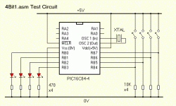
Honestly, this would be a trivial exercise in PIC programming - unfortunately I'm just too busy to get too involved right now. If no-one else does it, I might be able to do something next month when things are a bit quieter...
Actually, this is an ideal challenge for anyone who has been wanting to get into PIC programming, but has been lacking an idea for a simple "first project". To get you started, you can download a simple set of 4-bit counters from my WWW - there's even a version that deals with switches for up/down. You'll need to modify the code, because IIRC the counter wraps around from 0 to 15...
Good luck!
Mark
Attachments
- Status
- This old topic is closed. If you want to reopen this topic, contact a moderator using the "Report Post" button.
- Home
- Amplifiers
- Chip Amps
- Idea for a 255 step attenuator, is it good ?

