Note that the ON Semi devices are single BJT's. No darlington here... Hence, the lower Hfe. So you'll need driver transistors. This will make the thermal system more complex.
I am studying this thermal system. 49811+driver+TT. Some results are presented here http://www.diyaudio.com/forums/chip...me49810-11-thermaltrak-amp-9.html#post2131781. Please comment.
don't you find it a bit tricky to run the amplifier without any Zobel on the outputs? Did u check for oscillations?
I suggest for extra stability safety margin you mount at least one 5W10R together with 100nF from output to ground.
Sorry, forgot to mention. I run the output of the amp board to another PCB that contains output relay, DC sense & protection circuitry, a Zobel network (10R+100nF), and the output terminals. I had to put this stuff on a separate PCB due to space constraints in the chassis I was reusing. I use 1/4" quick disconnect terminals and AWG 14 (2.5 sq mm) wire between boards both for output and supply.
I think the 0.1R could be the cause of your bias stability issues with Q current higher than 60 mA per device. I recall Douglas Self muttering about that in his amp design book.
I'm sure Sanken's distributor in your area will be able to refer you to a place where you can buy the devices. I have dealt with B&D Enterprises. They seem to have a good selection of hard-to-get devices and were able to provide what I needed. Not the cheapest, but if you need it, you need it...
~Tom
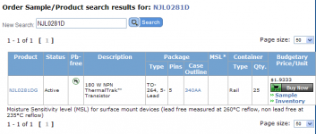
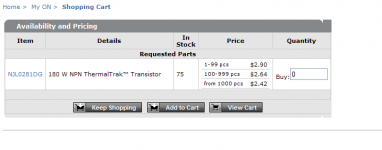
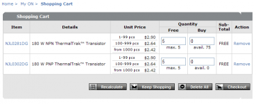
Actually, looks like $1.93 is a bug in ON's website. Volume pricing seems to be either 2.64 or 2.42. I'm with you on the samples.This is volume price. You need to pay $2.9 per device for less than 100 pcs. Better to get free samples.
Arrow quotes some good prices on the STD03s. No NPN parts in stock though.
Attachments
Folks,
I have previously tried the LME49810 with 2SC3281, 2SA1216 output devices, MJE340/350 drivers and failed, I figured I should try the LME49811.
MJE340/350 don t suit at all as drivers, as they are limited
to 50mA maximum, and even at this current, they are not good...
Use 2SA1837/2SC4793 instead...
Another (very good) solution is to use Sanken s darlingtons
2SB1647/2SD2560 or 2SB1648/2SB2561.
I could be interested in your rejects if the price is right. I'll only be using one pair per channel.Looks fine to me. To have enough to match i need at least 50 pieces anyway")
I could be interested in your rejects if the price is right. I'll only be using one pair per channel.
Yeah, i'll put the extra transistors here for sale. There wont be only the STD03s
at what ampere the it will work efficiently(when bridged) (60-0-60 at 5 A is it enough?)
I'm not sure I fully understand the question. I'm guessing it relates to the recommended size of the power supply transformer.
Two channels bridged running at +/-60 V will output about 500~550 W comfortably into 8 ohm. While doing so, about 200 W will be dissipated as heat. So you'll need to provide 700~750 W of input power. Give or take... (750 W)/(2 * 60 V) = 6.25 A.
That is if you run the amp rail-to-rail into 8 ohms. Should you decide that 400 W of output power is enough for you - and honestly, the difference between 400 W and 500 W (1 dB difference) is barely audible - then your 2 x 60 V, 5 A transformer will do just fine.
BTW, I calculated the power dissipated in the heat sink as Pdiss = (Vsupply^2)/(2*(pi^2)*RL); where Vsupply is the total supply voltage (120 V); RL is the road resistance (8 ohm); and pi is the ratio of a circle's circumference to its diameter (3.1415926...).
~Tom
the general rule is that the transformer VA be roughly between the maximum output power and twice the maximum output power.
A 60+60Vac 5Aac transformer, i.e. 600VA, will successfully power between 300W and 600W of total maximum output power.
But this is not a work/not work rule.
The transformer will be able to power amplifiers outside the 300 to 600W range
A 60+60Vac 5Aac transformer, i.e. 600VA, will successfully power between 300W and 600W of total maximum output power.
But this is not a work/not work rule.
The transformer will be able to power amplifiers outside the 300 to 600W range
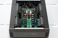
Musical Fidelity Titan bias
I think that Musical Fidelity are using a very simple solution. Looking at the picture of the Titan amp there is on pot per row of transistors. (the lower row can not bee seen in the picture) The amp consists of two amps i bridge configuration per channel. This bias solution will give the advantage of low cross over distortion as each row of transistors, 5 in each row, will be adjusted separatly. I think the pot is just connected to V+ (V- lower row) and the diodes in the 5 transistors in series and then to ground. Comments?
I think that Musical Fidelity are using a very simple solution. Looking at the picture of the Titan amp there is on pot per row of transistors. (the lower row can not bee seen in the picture) The amp consists of two amps i bridge configuration per channel. This bias solution will give the advantage of low cross over distortion as each row of transistors, 5 in each row, will be adjusted separatly. I think the pot is just connected to V+ (V- lower row) and the diodes in the 5 transistors in series and then to ground. Comments?
Attachments
Hi Pansons,
I am very curious how you will like them.
Subjectively and personally speaking, I prefer the STD mid-highs over the termaltrak's. For me in combination with the LME49810, the STD's sound faster, deeper and more alive (very analytical and detailed). On the contrary, I like the bass tightness and control better with the termaltrak's or the BPA300 chip designs. Of course it is all about implementation, But this are my observations with the same kind of implementation for all devices.
The STD03's are not easy devices and kind of limited in application.
I suggest if you work with the LME49810 as driver you make two variable bias adjusting points. One for the bias pins on the LME49810 (900 ohm fixed with 300 ohm variable in series) and a second variable one of 200 ohm between the diode string. The resistor value for the bias pins of the LME49810 is around 1K to obtain the 2.5mA pre bias current. But slight variations in this resistor make the whole bias to rise or slow significant till a degree that there can be danger or under bias. Therefor you want to fine adjust this value. Please trust me on this, I've bin there done it, and blow them twice A good note is, that a STD03 blows friendly and softly, and often break inside the die even before the fuse blows. So no spectacles
Good luck! And I look very forward to your measurements and listening impressions.
With kind regards,
Bas
I am very curious how you will like them.
Subjectively and personally speaking, I prefer the STD mid-highs over the termaltrak's. For me in combination with the LME49810, the STD's sound faster, deeper and more alive (very analytical and detailed). On the contrary, I like the bass tightness and control better with the termaltrak's or the BPA300 chip designs. Of course it is all about implementation, But this are my observations with the same kind of implementation for all devices.
The STD03's are not easy devices and kind of limited in application.
I suggest if you work with the LME49810 as driver you make two variable bias adjusting points. One for the bias pins on the LME49810 (900 ohm fixed with 300 ohm variable in series) and a second variable one of 200 ohm between the diode string. The resistor value for the bias pins of the LME49810 is around 1K to obtain the 2.5mA pre bias current. But slight variations in this resistor make the whole bias to rise or slow significant till a degree that there can be danger or under bias. Therefor you want to fine adjust this value. Please trust me on this, I've bin there done it, and blow them twice
A good note is, that a STD03 blows friendly and softly, and often break inside the die even before the fuse blows. So no spectacles Good luck! And I look very forward to your measurements and listening impressions.
With kind regards,
Bas
Hi Pansons,
The STD03's are not easy devices and kind of limited in application.
Hi Bas,
Thank you very much for your valuable advices.
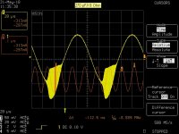
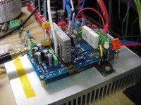
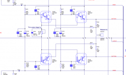
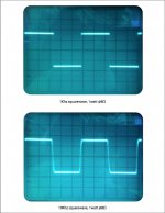
I initially will use 49811 with one pair 03N/03P. Referring to your schematic shown in post 3 of the thread, you put caps C11 and C12 across the base pins. Did you put them there in concept design stage? Or trail and error? I find that without cap my test unit will oscillate when loaded by just a small cap, 270 pF//8 Ohm. The waveform is shown below. I did not encounter such problem with ThermalTrak. Is it because of the super high current gain of 03N/P?
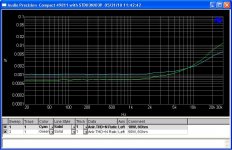
The test unit and its THD+N vs freq for 18W/50W into 8 Ohm are shown below.
Panson
Attachments
Hi Bas,
Thank you very much for your valuable advices.
I initially will use 49811 with one pair 03N/03P. Referring to your schematic shown in post 3 of the thread, you put caps C11 and C12 across the base pins. Did you put them there in concept design stage? Or trail and error? I find that without cap my test unit will oscillate when loaded by just a small cap, 270 pF//8 Ohm. The waveform is shown below. I did not encounter such problem with ThermalTrak. Is it because of the super high current gain of 03N/P?
The test unit and its THD+N vs freq for 18W/50W into 8 Ohm are shown below.
Panson
Dear Panson,
If I understand you well, if you put "any" cap between the base pin's you get oscillation?
My attempt with putting those cap's is to improve switching behavior of the transistors. But that I have no experience with the LME49811. I never tried it without those capacitor, and I have to admit I got this Idea from Arcam, who does the same trick in the P1 amplifier. See attachment.
Maybe the LME49811 doesn't like this capacitive load.
The second attachment is square wave reproduction with the cap's on a resistive load on my actual design. The compensation here was only 10pF but I have to admit this was on the edge! With some messy loudspeaker leads I got oscillation as well. This was solved however with going safe with 22pF.
With kind regards,
Bas
Attachments
Last edited:
If I understand you well, if you put "any" cap between the base pin's you get oscillation?
Hi Bas,
Without cap between the base pins, I get oscillation with capacitive load.
Today, I read a Chinese article reviewing Musical Fidelity A1 2008 edition. The amp uses one-pair STD03N/03P per channel. According to reverse engineered schematic, it does not have such cap surrounding 03N/03P. The bias generation consists of the 03N/03P diodes in series with two 1N4007 and a 200 pot. The emitter resistor is 0.22 R. Bias current is about 600 mA.
Article link http://home.hdavchina.com/space.php?uid=1&do=album&picid=14465&goto=down
Panson
Last edited:
Hi Bas,
Without cap between the base pins, I get oscillation with capacitive load.
Today, I read a Chinese article reviewing Musical Fidelity A1 2008 edition. The amp uses one-pair STD03N/03P per channel. According to reverse engineered schematic, it does not have such cap surrounding 03N/03P. The bias generation consists of the 03N/03P diodes in series with two 1N4007 and a 200 pot. The emitter resistor is 0.22 R. Bias current is about 600 mA.
Article link ÎÞÏßµçÓëµçÊÓ10Y04 (8) - ¡¶ÎÞÏßµçÓëµçÊÓ¡·2010 µÚ4ÆÚ - Ïà²á - admin - Ó°ÒôÖйú ¡ª Ó°Òô°®ºÃÕߵļÒÔ° - ´óÐÍÓ°Òô°®ºÃÕß¡¢¼ÒÍ¥Ó°Ôº¡¢µçÓ°¡¢CDµúƬÍæ¼Ò¡¢DIYµ¨»úÍæ¼Ò¡¢HIFI·¢ÉÕÓѵĻ¥¶¯Æ½Ì¨¡£
Panson
Dear Panson,
Thank for this link, can you point me to the part where they show the schematic? It is a labyrinth for me
If someone has lot's of experience with those sanken's then it must be Musical Fidelity, since they use them for for ages Furthermore, Did you use/try small compensation cap's between base and collector? I got oscillations without them. You can try base stoppers of a few ohm.
I think the system shouldn't oscillate without capacitance, so to be honest it is a mystery for me as well but I think parasitic's play a part, combine that with the huge total hFE of the Sanken's u can get in trouble faster then you wish for. In my case my amplifier self destruct itself a few times, but all of that was solved after increase the miller cap to 22pF, And adding 47pF compensation between base and collector. In my case the oscillation also happened with capacitive loads caused by different type of speaker wire. That is why I said the STD3's can be a bit difficult to tame
With kind regards,
Bas
Last edited:
Dear Panson,
Thank for this link, can you point me to the part where they show the schematic? It is a labyrinth for me
Furthermore, Did you use/try small compensation cap's between base and collector? I got oscillations without them. You can try base stoppers of a few ohm.
I think the system shouldn't oscillate without capacitance, so to be honest it is a mystery for me as well but I think parasitic's play a part, combine that with the huge total hFE of the Sanken's u can get in trouble faster then you wish for. In my case my amplifier self destruct itself a few times, but all of that was solved after increase the miller cap to 22pF, And adding 47pF compensation between base and collector. In my case the oscillation also happened with capacitive loads caused by different type of speaker wire. That is why I said the STD3's can be a bit difficult to tame
With kind regards,
Bas
Hi Bas,
The schematic is shown in another issue which is not available from the website. I can scan it and e-mail to you. Please let me know your e-mail address.
I have base stopper resistors already, but did not try putting cap across C and B pins. This is effectively adding a Miller cap in the output stage for which I don't feel "right". I might do that eventually for this Sanken part and/or other high-gain Darlington.
I am in line with you that the amp (simple topology) should not have so many caps around.
Cheers,
Panson
- Status
- This old topic is closed. If you want to reopen this topic, contact a moderator using the "Report Post" button.
- Home
- Amplifiers
- Chip Amps
- Yet Another LME49811 + STD03 Build