as a BPA300 group buy veteran, I'm still struggling with problems I would like get rid of but don't know how.
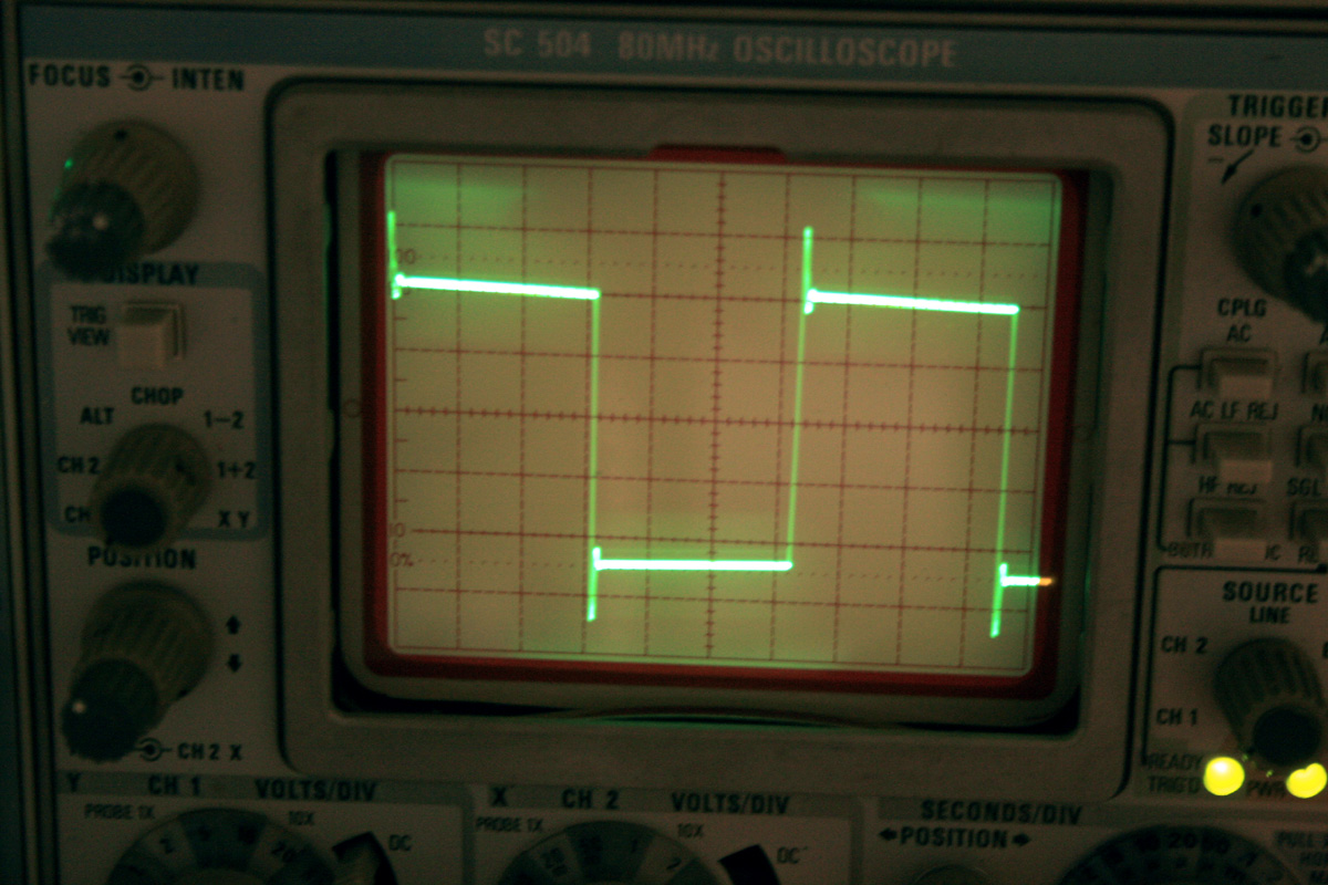
to state the problem in simple terms, using the default components values, when a square wave of ~400 Hz is played at the input, a ringing effect is watched with an oscilloscope at the output, at a single PA150 board solely connected to the PS.
installing larger NFB capacitor (15pF instead of the recommended 8pF) smooths the ringing but also kills the frequency response. both the ringing and the worse frequency response are audible.
having another board (a clone bought on ebay before PA saved the day) and some spare parts, I was determined to track the problem without ruining the existing completed boards.
Unlike the first attempt that was in success-oriented mode (meaning everything was built and installed into chassis before measurements taken place), I now placed the LMs without installing the output resistors and without DC offset canceling trimmers (direct connection to ground on non-inverting input). guess what - I had 22, 26 and 40 mV dc on the three outputs BUT the square wave was perfect. I installed the trimmers (100K - lesson learned from the previous attemt with 50K) and brought the offset to 0 on all. that required a lot of back and forth resistance changes since there is coupling between LMs (why?).
now I had zero offset but ringing on edges of the square wave. the amplitude is influenced by the amount of offset correction applied - more correction, larger ringing amplitude.
in despair I shuffled some wires and turned the circuit into a non-inverting one. installing a feedback capacitor to ground I managed 12, 15 and 30 mV offset and nice square wave.
How can I have get rid of the dc offset without compromising response? I have all components from the same batch (same batch number) but obviously not matched. is there a way to mach without soldering them into the circuit?
Need to mention also that the FB resistors are 200k and 10k 0.1%.
This is an interesting problem and I have yet to look at my boards with a square wave... but I will try to do that this weekend and get back on it. I have to say they are still some of the best sounding boards I;ve ever listened to though so I suspect mine are not suffering from the ringing problem. I always thought this project should have included a servo on each chip and this may be the answer to the problem, especially if I find that mine are doing the same thing. I believe it could be built on a small board and then wired in with the small board mounted piggyback on the bottom of the BPA-150. If I find any ringing I'll post scope pics and we can compare... Also, as far as my offsets go they were similar to yours and all my chips were also from the same batch... I was also able to get it nulled out by going back and forth but I also noticed some slight drift.
Mark
Mark
Last edited:
sonic effect of ringing
to my ears, the ringing manifested itself most in double bass plunking in high quality jazz recordings. where I was accustomed to hear the attack related to plunking when the bass takes lead no I hear somewhat boomy sound. in some sense I would expect edge enhancement, like similar effect on images but maybe our auditory sensation differs in that from our visual system.
to my ears, the ringing manifested itself most in double bass plunking in high quality jazz recordings. where I was accustomed to hear the attack related to plunking when the bass takes lead no I hear somewhat boomy sound. in some sense I would expect edge enhancement, like similar effect on images but maybe our auditory sensation differs in that from our visual system.
YEP! Mine is also ringing. I think we have some work to do here. First one is 1khz 10 watts, second one 10khz 10 watts. Both into 8 ohm resistive load.
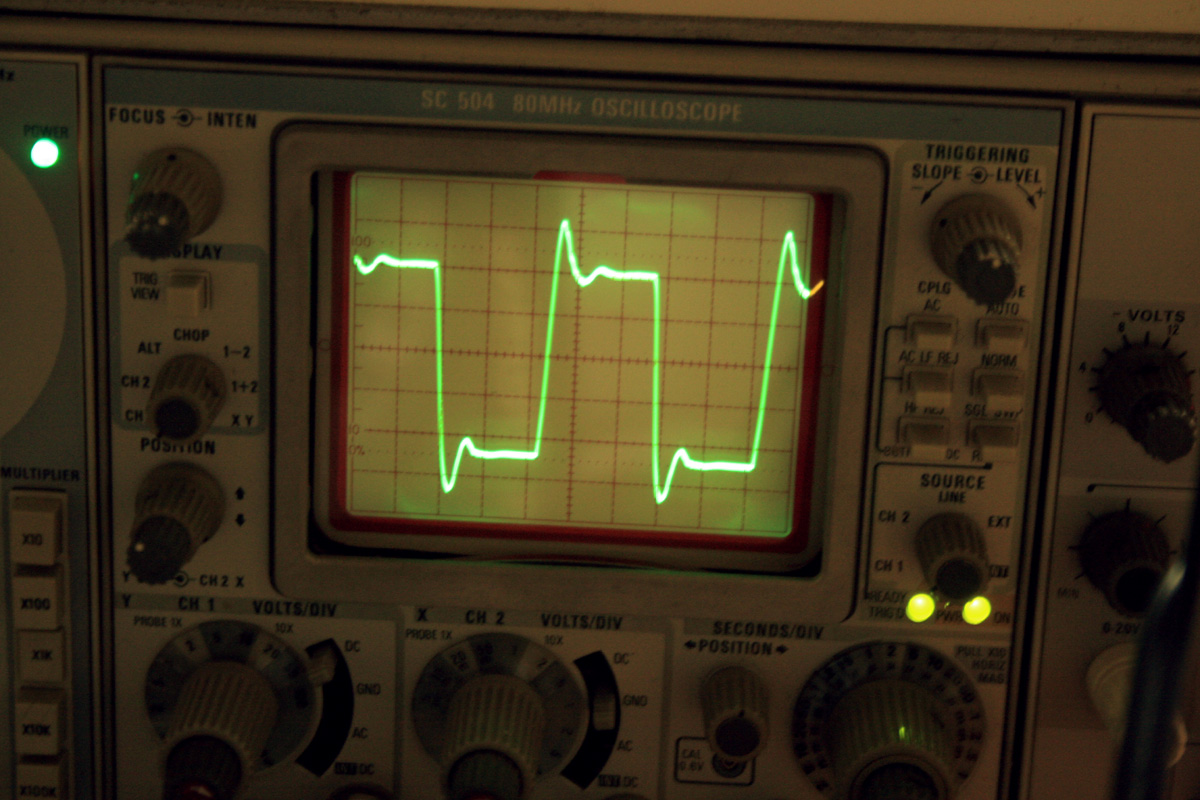
How does your insignal look like? It's very important to compare input and output. Are the probes adjusted properly?
input signal
in my case the input signal looks like perfect square wave, taken from a proper signal generator. moreover, if the trimmers are shorted, meaning non-inverting input goes right to ground, the output of each LM has no ringing (done with no output power resistors). I felt somewhat alone in this until now. I am much more relieved now that other have witnessed the phenomenon and better skilled people will be looking for a solution.
in my case the input signal looks like perfect square wave, taken from a proper signal generator. moreover, if the trimmers are shorted, meaning non-inverting input goes right to ground, the output of each LM has no ringing (done with no output power resistors). I felt somewhat alone in this until now. I am much more relieved now that other have witnessed the phenomenon and better skilled people will be looking for a solution.
Last edited:
Be careful with square wave tests. If you don't limit the rise and fall times of the input, all sorts of unexpected things can happen. Think about the slew rate of the input signal, then convert that to frequency. I think you'll find you're up in the RF region. See if limiting the slew rate a bit gives a huge improvement in the output. If that's the case it may not be important. If it really is affecting the audio, you might try fooling with the output network values. (I don't have this circuit, so can't be specific, but most amps like about .1uF in series with an inductance, and the value of that inductance needs to be above a minimum value- there was a huge thread on this some months (years?) back.)
P.A., Yes input square wave is more or less perfect. Scope connection was direct hook up across the load resistor as I normally do. I do have an input capacitor of 5uf. So I didn't show low frequency response which does exhibit some roll off. I disagree this is a rise and fall time problem in and of itself. I'm thinking something else in the circuit is causing(inducing)this to happen This is the only amp I have here out of more than half a dozen that looks like this. The rest of them reproduce more or less perfect square waves.
I have the Lundahl input transformers to bridge these into mono and it gets rid of the input cap. This is the next step I'm trying... beyond that a servo on each 3886 may be the only way out of this mess.
I have the Lundahl input transformers to bridge these into mono and it gets rid of the input cap. This is the next step I'm trying... beyond that a servo on each 3886 may be the only way out of this mess.
Last edited:
Scope connection was direct hook up across the load resistor as I normally do.
I have the Lundahl input transformers to bridge these into mono and it gets rid of the input cap. This is the next step I'm trying... beyond that a servo on each 3886 may be the only way out of this mess.
Mark, from the above I gather you measure the bridged configuration - is your scope input floating? otherwise you cannot measure across the load resistor of the bridged amp since you cannot connect the ground to any of the terminals.
No, I'm not bridged as of yet but I'm wondering if bridging the boards might not cancel out the peoblem...
I started bridged. the non bridged is only after I started tracking the source of the problem, thinking it may be caused by bridging that leads to some ill interaction between the LMs
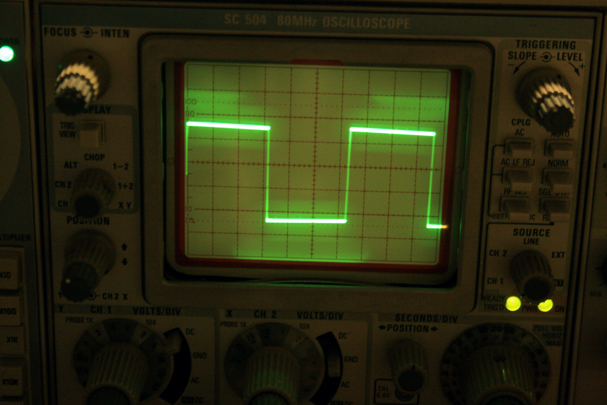
I believe I've found the answer to the problem. There is very definately some interaction between the 3886's although I'm not sure exactly what is causing it. What I did to get the waveforms shown here was to use the offset pots to null out the overshoot and ringing going back and forth between the three pots. Note that the ringing may get worse before it gets better as you go back and forth.... then you all of a sudden find the null points of each chip and you can almost make it perfect. Use the scope in X10 magnification to spread out the leading edge! It takes a bit of doing but seems to work out well. My offset in single chanel mode was .04 volts per channel with the ringing nulled out and in bridge mode as measured between the positive binding posts was .0002 volts which is quite impressive to say the least. It seems the null is more important than the actual offset but things seem to end up where they belong. You end up with extremely low offset in the end since in bridge mode you are merely measuring the difference in offset between the two amplifiers. I heard similar things as you heard with the exaggeration and so on but I have not listened to it yet with things looking normal but things should sound 100% better now... Ultimately this should probably be done using a distortion analyzer while looking at the actual distortion content on a scope. Hopefully it can be adjusted for even harmonic distortion content...
I hope this helps you out...
I hope this helps you out...
Last edited:
dc offset between LMs
Mark,
if you just pulled out all trimmers and made a short to ground instead of each trimmer, you will get this nice wave form, BUT, you will also have a dc offset (40mV max. in my, and also yours as you write, case) which is different for every chip (between 20 and 40) . this in turn translates to current that flows from one chip to the other causing the chip to get hotter than needed.
I wish to both remove this difference AND have a nice wave form. I agree completely that the value of the common offset, if about the same in each module, nulls across the loudspeakers' terminal and is no real concern.
What happens if you decouple every pot with 100 nF/63V?
PA, not sure I understand. where to place this capacitor (and still have the required DC)?
I think he means placed across each trimmer. You can't place a capacitor in line with each trimmer because from a DC standpoint it's out of the circuit. The thing I thought was odd when I first got my boards going was the fact that the trimmers ended up at the far end of the adjustment range to get them close to zero offset. Some will zero out perfectly and some wouldn't. With the null adjusted the pots are now in mid range somewhere. I find that doing the null doesn't make it run any hotter than it did before and although the offset of each card is a tad bit out of spec the offset of the bridged pair is actually better then good which is what the designer mentioned in his posts here on DIY and perhaps on his web page site. My amp runs very cool into my 6 ohm Dynaudios, even after 2 hours of fairly hard use... I took some time to listen to it last night and it sounds 100% better than it did, still extremely quick, great detail and you can really listen in to the music much better than with my Aleph amplifiers. My gut feeling is that nothing is going to properly take care of this except the use of servos as NS reccomends in their white paper. A modification for that wouldn't be too difficult to pull off or very expensive and then the job is properly done.
Mark
Mark
Last edited:
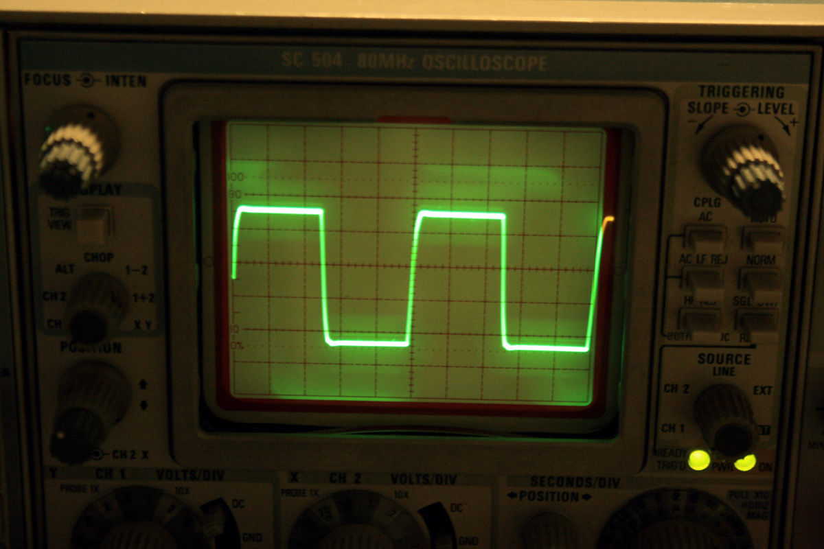
I meant 100 nF across the pot. You could use a 0805 or a plain polyester on the solderside.
Bingo! shorting ac to ground does the trick. however, I had the feeling 100n causes early roll-off in high frequencies. I installed 3.3n (simply because I had them) and have frequency response almost flat to 40KHz.
I cannot explain any of this, but I don't really care at this point. I manage to bring all LMs to 13-15mV on two boards with no ringing and reasonable frequency band.
unfortunately I run out of these capacitors. I see a components shop in my near future.
in order not to contribute the findings (100n vs. smaller caps) to the late hour and wishful thinking I will verify it tomorrow 🙂
Well, that sort of makes the null thing a bit strange! I am about to pull mine apart and do the same thing...
- Status
- Not open for further replies.
- Home
- Amplifiers
- Chip Amps
- Parallel LM3886 problem