I've tried .1uf on one board and 10uf on the other... looks about the same. There is still a tiny bit of ringing with either of these values when you crank the scope gain way up and look at the top of the waveform. I'll have to get some other caps tommrrow and I will try both 33uf and 100uf to see exactly how much it takes to clean it up 100%. Also, if you adjust offset the amount of ringing still varies slightly.
Mark
Mark
There is still a slight ringing when you increase the gain of the scope and look at the top. I've tried four values of caps now. .1uf, 10uf, and 33uf, and 100uf and all of them seem to more or less have exactly the same effect. None of them changes the hf roll off at all. Square wave stays the same. Slightly different amounts of ringing though.... This ringing can still be tuned out by using the pots to null it at the expense of slightly higher offset. With offset as good as it gets it's about .021mv. I think I'll go back to the .1uf film caps... they seem to work best and this is apparently a hf problem of some sort. The large electrolytics across the pots cause a very long response time when adjusting and they seem to make the amp run a bit hotter for what ever reason. The caps added in make the amp usable but it is still far from perfect. I might try the N.S. BPA-100 layout for the servo on this. I won't have time till between xmas and New Years to fiddle with it much more though.
With .1uf film cap...
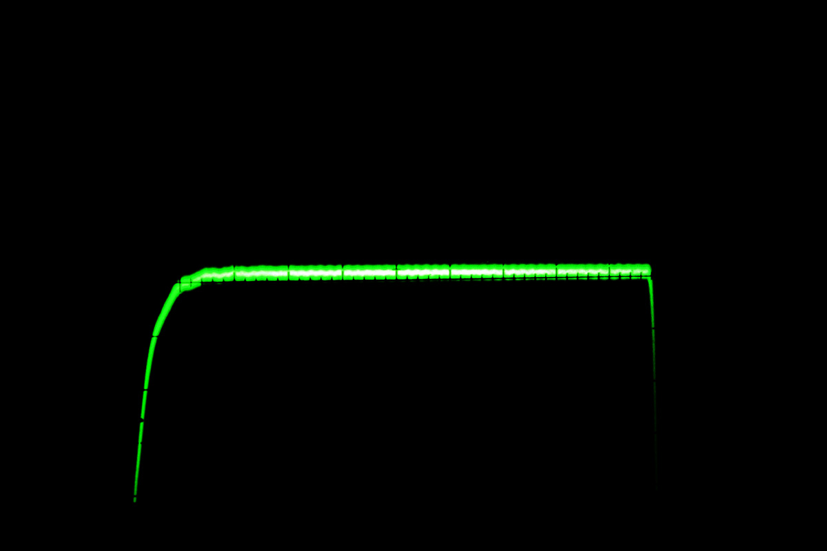
With 100uf electrolytic cap...
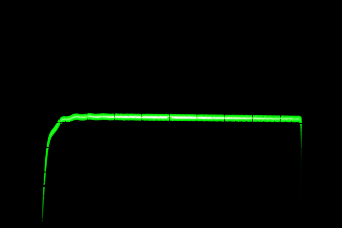
With .1uf film cap...
With 100uf electrolytic cap...
The ringing is quite subtle and might not matter, especially if it's at a relatively high frequency.
What is the frequency of the ringing? (Or what was the sweep control on the scope set to, in us/div? It looks like about 2 cycles per division, for the ringing, at the sweep speed setting you were using.)
What is the slew rate of the vertical portion of the input square wave? What is the slew rate of the vertical portion of the output square wave? (Use a faster sweep rate to expand horizontally and find the slope in vertical divisions per horizontal division, and use the vertical attenuator's v/div setting and the horizontal sweep's us/div setting to calculate v/us.)
Can you post the schematic? (or a link to it)
The ringing might also be inductance-related. Did you trim off the caps' leads, when testing with them? You probably did. And have you tried a very small resistance in series with the caps? And do you have a Zobel network on the output?
Have you looked for the ringing at the feedback input pin of the chip, and at the signal input, and on the power supply pins? (If your scope has two channels, maybe you could even compare the ringing frequency's relative phase at different points, such as input pin and feedback pin, if there's any present at the input.)
Do you have a low-pass RF filter, very near the chip's input pin? If not, you should probably try one, even just temporarily, that limits the input's slew rate so that the output does not try to exceed the chip's published minimum guaranteed slew rate.
Fast square waves are good for exciting potential areas of instability. But in your case it might not need much further practical consideration, if it's a high-frequency mode that will probably never be excited during normal use. Almost all amplifiers will exhibit ringing like that, if you bang their inputs hard enough. Yours actually looks pretty good, already, if the ringing is at a very high frequency.
To find the input filter cutoff frequency needed to impose a particular slew-rate limit on the output, look at post #1984, in the thread at the following link:
http://www.diyaudio.com/forums/soli...terview-error-correction-199.html#post1223767
You should be able to use the desired maximum output slew rate (i.e. the minimum guaranteed slew rate spec from the LM3886 datasheet: either 8 v/us or 19 v/us), the output voltage swing, and the gain, to calculate the desired maximum input slew rate, and then use that and the input voltage swing and the equation I gave in that post to calculate the input low-pass RC filter's cutoff frequency. Or, you could just try 100 kHz and see if the ringing is gone, and go up or down from there and see what cutoff frequency is needed to kill it.
All of that is assuming that the high frequencies in the input square wave are exciting some high-frequency instability. If that's the case, then you should probably keep the input RF filter (I would keep it anyway.). There are probably also ways to cure the instability itself, if that's what it is. But that's probably not going to be necessary. (Also keep in mind that your scope probe could even be changing the circuit enough to cause the ringing, if it's at a very high frequency. How long is your ground lead, for example?)
- Tom
Last edited:
Tom,
Thanks for your very helpful suggestions. That is a 10khz square wave at a few watts out into an 8 ohm dale non-inductive load resistor. The scope is a TEK 2465 and X10 TEK probe although I don't recall the probe model # off hand. Input wave is clean on the scope. I'm tending to agree with you that the input slew rate needs to be limited as there is no input network at all. Schematic here....DIY BPA300 6x LM3886 300W audio Amplifier
Thanks for your very helpful suggestions. That is a 10khz square wave at a few watts out into an 8 ohm dale non-inductive load resistor. The scope is a TEK 2465 and X10 TEK probe although I don't recall the probe model # off hand. Input wave is clean on the scope. I'm tending to agree with you that the input slew rate needs to be limited as there is no input network at all. Schematic here....DIY BPA300 6x LM3886 300W audio Amplifier
Tom,
Thanks for your very helpful suggestions. That is a 10khz square wave at a few watts out into an 8 ohm dale non-inductive load resistor. The scope is a TEK 2465 and X10 TEK probe although I don't recall the probe model # off hand. Input wave is clean on the scope. I'm tending to agree with you that the input slew rate needs to be limited as there is no input network at all. Schematic here....DIY BPA300 6x LM3886 300W audio Amplifier
Mark,
Have you tried it yet, even just with a simple RC lowpass filter with a guesstimated cutoff frequency of something like 200 kHz?
It would be really helpful if you could say what the frequency of the ripple was, or what the timebase setting was.
Tom
Correct me if I'm wrong here. In some cases people end up adding a low-value cap between the inverted and non-inverted input of the amp, in order to avoid some oscillation problems and equipment turn-off/on interference.
The values are usually between 220 and 300 pF, high-quality caps.
I wonder if this would help in the given situation, considering they're supposed to eliminate only very-high frequency interference?
The values are usually between 220 and 300 pF, high-quality caps.
I wonder if this would help in the given situation, considering they're supposed to eliminate only very-high frequency interference?
Tom,
Thanks for your very helpful suggestions. That is a 10khz square wave at a few watts out into an 8 ohm dale non-inductive load resistor. The scope is a TEK 2465 and X10 TEK probe although I don't recall the probe model # off hand. Input wave is clean on the scope. I'm tending to agree with you that the input slew rate needs to be limited as there is no input network at all. Schematic here....DIY BPA300 6x LM3886 300W audio Amplifier
I just realized that you said that the square wave was 10 kHz. So the time for half of one cycle, roughly 10 divisions, is equivalent to 20 kHz. So one horizontal division is equivalent to roughly 200 kHz. And there are about two cycles of oscillation per division, making the oscillation around 400 kHz.
You don't need or want to enable that high frequency to be excited within your system. I would probably just band-limit the input with a simple RC low-pass filter, with a cutoff frequency that is as high as possible while still killing the oscillation. I'd probably use a relatively-low-value metal film resistor in series with the signal path, for less noise and less effect on offsets, followed by a capacitor to ground, close to the input pin. But in your case it would be tempting to put it before the junction of R2, R5, and R11 in the schematic you gave, and just have one filter.
On the other hand, you could use the 10k resistors, themselves, and scale the C values (see below) downward. A capacitance of .0001 uF (100 pF) to ground after each 10k resistor (R2, R5, R11 in your schematic) would give low pass filters with f(-3dB) at about 159 kHz, for example. However, I think that the C to ground, there, might be a problem for inverting inputs (possible oscillation tendency). So I'd probably actually want to replace each 10k with two 5k resistors, and put a capacitor of about twice the value to ground, between the two resistors. e.g. 5k - 200 pF(to ground) - 5k - inverting input, instead of 10k - 100 pF(to ground) - inverting input. So maybe the first idea was better, in this case, i.e. having just one filter, farther upstream.
You probably know all of this already, but, the size of the resistor and the cutoff frequency will limit your choice of capacitor type. For example, 100 Ohms in series followed by 0.01 uF (0.009 uF, actually) to ground would give a cutoff frequency of 180 kHz. So that wouldn't be an electrolytic. You could also scale either the R or the C or both to adjust their values and/or the frequency, since f(-3dB) = 1/(2*Pi*R*C). So halving R or C would double the frequency, for example, and halving R and doubling C (or doubling R and halving C) would not change the frequency, etc.
Last edited:
I was trolling through old posts and found this, which addresses some of the issues of slew rate limiting, for amplifier testing:
http://www.diyaudio.com/forums/solid-state/117469-square-wave-testing-slew-rate.html
http://www.diyaudio.com/forums/solid-state/117469-square-wave-testing-slew-rate.html
Did I understand the elementary part of this is?:
(paraphrase)
For inverting amp, the non inverting input to ground can be a variable resistor to set for 0 dc offset AND the overshoot is corrected/reduced by placing 3.3nF in parallel with the variable resistor?
(paraphrase)
For inverting amp, the non inverting input to ground can be a variable resistor to set for 0 dc offset AND the overshoot is corrected/reduced by placing 3.3nF in parallel with the variable resistor?
Last edited:
Hi Y'all,
I was just think about building another LM3886 amplifier (after a long time) when I ran into this thread, thanks all, great stuff.
danielwritesbac,basically, you got it right.
In general the resistor at the non-inverting of an opamp is used to balance the dc offset. The rule of thumb for the value of this resistor is the parallel combination of the feedback resistors connecting output to inverting input to ground. This resistor is also a known noise source.
A capacitor connected in parallel to this resistor will not affect the dc performance, but will roll off (short out) the higher frequency signals at the positive input.
As a probably dumb question: "Has anyone tried this circuit with feedback components that are more in line with the values recommended by National Semiconductors, and reflected in standard implementations of the LM3886 as e.g.: the Elektor version?" It may well be that changing the design feedback components by an order of magnitude worsens the transient behaviour of this circuit. As Tom (gootee) seems to point out it is back to the seventies and all the fine discussions about slewrate and TIM.
Regards,
- Status
- This old topic is closed. If you want to reopen this topic, contact a moderator using the "Report Post" button.
- Home
- Amplifiers
- Chip Amps
- Parallel LM3886 problem