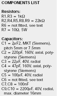
C3 is too low in value. Try >=72uF
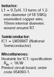
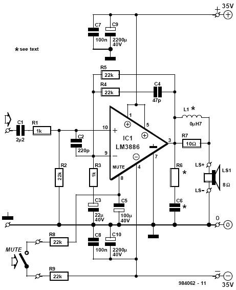
R6 &C6 are specified on the National datasheet.
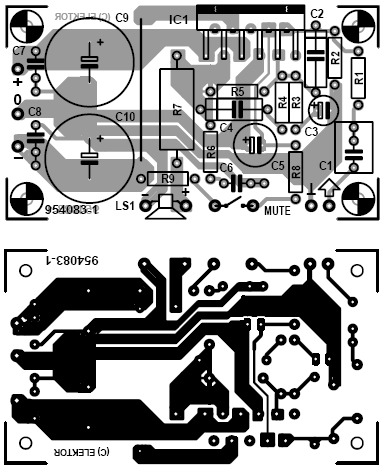
Separate the signal ground from the power/decoupling/zobel/mute/speaker ground.
C3 and R2 must go direct to the signal input return/ground pad. Nothing else may be on this dedicated ground reference.
R6 &C6 are specified on the National datasheet.
Separate the signal ground from the power/decoupling/zobel/mute/speaker ground.
C3 and R2 must go direct to the signal input return/ground pad. Nothing else may be on this dedicated ground reference.
then the 2u2F at the input is wrong. F-3dB~3Hz
I'd prefer to keep the input cap and change the NFB cap to suit. My real preference would be 4u7F for the input and 150uF or 220uF for the NFB.
Otherwise the amp will develop some AC voltage across the NFB cap and thus increase avoidable distortion.
C3 >= sqrt(2) * C1 * [R2+R1] / R3
The ratio of R3 to R2 determines the ratio of C3 to C1.
yes, it's small and has place for all the 'unnecessary' components, whether you fit them or not.it is a working circuit from elektor electronics
I have used it myself once in a multichannel project.
Small, cheap, fast to build and reliable operating...no complaints from me so far.
Regards
you'll believe everything you read on the net!According to the original article, with a regulated supply (+/- 35v) they got 100 watts rms from this circuit!!!
100W into 8r0 requires an output of 40Vpk and 5Apk.
How does one get this from +-35Vdc whether regulated or not?
... please, could write in proper english? I'm not familiar with this chat english.... its y i hav written make it complete....
it's not chat, it's not english language, it's gibberish.I'm not familiar with this chat english.
OK. Now Please give me the answer of few question if u dont mind. (1) No one said that the pcb design is fault. Its mean i can make pcb. (2) The only thing indicate by the members her is the values of capacitors. there is no need to change in pcb design to adjust these values?
Last edited:
it's not chat, it's not english language, it's gibberish.
I think that it's some form of cell-phone texting.
I don't think that we should demand proper English. Some of our members don't get to write or speak English often. But I think that a poster should try their best.
From the LM3886 Datasheet (Layout, ground loops and stability section); ''When designing a layout, it is important to return the load ground, the output compensation ground and the low level (feedback and input) grounds to the circuit board common ground point throught separate paths. Otherwise, large current......''
Someone can tell me if the design respect this rule????
Someone can tell me if the design respect this rule????
Some Flaws in PCB Design? But i want a sound like professional audio systems such as creative and altelancing or edifier. I am in Asia and here in my country this lm3886 and lm4780 ic is much cost. Its y i need a perfect design and values of components. I wana use 1 lm2886 for left one for rite and may be if i hav more money one for subwoofer. i have 2 8ohm 6 inch woofer speaker. Can u tell me plz the power in ohm and size of the tweeter or also a mid if needed. the subwoofer will be 8 ohm or 4 ohm (which value will be best) 8 inch woofer speaker. Also the minimum recomended power supply for 4 lm3886 ics working at full power in same time. i mean volt and how much ampere. As i think the 35-0-35 and 5 ampere transformer is needed. I can arrange big speakers later so i need to know the powe i neede if the all ics are working at full power
There is no "best" PCB design, it's only the best compromise. WhenI said the PCB has some flaws, I meant that I would do it in a different way. The sound will be better than the one you're used to hear in the stuff available on the market. Make the PCB as it is and don't use more than +/-30V rails if you intend to drive also 4 ohm speakers. This chip is very good, you have nothing to be afraid of. I also suggest to put 10k resitors for R8 and R9 (or simply strap one of them) as they are placed in series. 44k is too much for the mute pin.
- Status
- This old topic is closed. If you want to reopen this topic, contact a moderator using the "Report Post" button.
- Home
- Amplifiers
- Chip Amps
- Lm3886 pcb


