I went through a similar struggle when transitioning from Siva's board to the FE - different PCB setup. Assuming the wire functions are correct, what about you developers using different size fastons for power inlets in future offerings? Pretty fail-safe with speaker pads.
Last edited:
"..I may have interchanged PGND with AC1 or 2 in error and in haste.."
More likely an explanation as the boards are well proven and excellent.
But it still bites.. Sorry to hear.
Yeah think I'm gonna run with this as the most likely explanation for now
 Tbh I'm not too bothered about making mistakes as it's quite instructional so long as it don't cost me my health or my wallet too much, which it hasn't. I'm in it as much for the intellectual stimulus as much as for getting a decent sounding amp for a decent price!
Gonna concentrate now on getting my second board up and running properly with aforementioned changes to R1,R4,C13 and anything that springs to mind from various optimized BOMs around here. Per ardua ad astra as they say

I went through a similar struggle when transitioning from Siva's board to the FE - different PCB setup. Assuming the wire functions are correct, what about you developers using different size fastons for power inlets in future offerings? Pretty fail-safe with speaker pads.
FE = Fremen Edition, Bob?
Yes, You can read about it in the posts before and after THIS ONE.
Fantastic. That's a bookmark in my browser for sure. Always good to gain from another's struggles. The layout of your pics at post 155 in that thread is precisely what us newbs need to see. I was happy also to confirm from the phasing tutorial that my traffo is indeed in phase.

It's not just the colors that matter. You need a meter or continuity tester to determine which wires to select. A Pair of wires that makes the meter beep/light up is considered in my words -a circuit. Once identified I usually mark both of those with a black magic marker, tape or colored heatshrink tubing. Then check the other two to confirm continuity in that second pair. The psudo-CT is made from combining one wire from each pair. I'd feel really shaky trying to do it with colors only.
Last edited:
It's not just the colors that matter. You need a meter or continuity tester to determine which wires to select. A Pair of wires that makes the meter beep/light up is considered in my words -a circuit. Once identified I usually mark both of those with a black magic marker, tape or colored heatshrink tubing. Then check the other two to confirm continuity in that second pair. The psudo-CT is made from combining one wire from each pair. I'd feel really shaky trying to do it with colors only.
Well blow me. I've only ever worked with properly labelled traffos and always laboured under the assumption that the second of the first pair of secondaries always joins to the first of the second pair and was in phase. DIY mags do that for you
. I really should go and build the Decibel Dungeon bulb tester.The bulb tester is essential (I have 3 styles), but I hope you are not confusing functions. The test I described can be done with that, but it's primary use is preventing damage at first power-up when the transformer is connected to an amp. A simple 1.5V flashlight battery and a bulb can be used as a continuity tester of you don't have a meter with that function.
Attachments
Last edited:
The bulb tester is essential (I have 3 styles), but I hope you are not confusing functions. The test I described can be done with that, but it's primary use is preventing damage at first power-up when the transformer is connected to an amp. A simple 1.5V flashlight battery and a bulb can be used as a continuity tester of you don't have a meter with that function.
I was ahead of myself and referring in my head at least back to my accident! I have identified my pairs with a meter. I have used a 1.5 battery and bulb as a continuity tester myself in the past. I'd better move across into the slow slow lane and do more basic research so the fast boys can get thru. This thread was buidling up quite a head of steam till I came along with my banalities
. Thanks again for your help and sorry to everyone who has had to read my woes.You have nothing to apologize for. That's how we all learn and it's how problems get resolved. There always seems to be others who benefit from these conversations even though they may not be actively posting at the moment. Safety for the project and the builder (and family members) has top priority, so please don't hesitate to post any question or problem description that presents itself.
Last edited:
You have nothing to apologize for. That's how we all learn and it's how problems get resolved. There always seems to be others who benefit from these conversations even though they may not be actively posting at the moment. Safety for the project and the builder (and family members) has top priority, so please don't hesitate to post any question or problem description that presents itself.
My absolutely final parting shot on the subject. Get the manufacturer's data sheet! Why oh why didn't I think of that first.

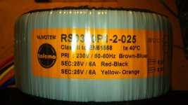
Dario recommends 24 or 25V transformers in the build guide. I usually buy from airlink transformers in the UK and they state input voltages of 230V, my mains is steady at 245V and I find I get close to 24V from a 22V rated transformer. My current speakers are rated at 6 Ohm, any future replacements are lightly to be 6 or 8 Ohm so I think I need to order a couple of 2 x 22V 225VA transformers. Can anyone find fault with my logic before I go any further, I would hate to order two transformers which I can not use.
You are right to take account of your typical supply voltage.
A 230:22+22Vac transformer operated on a 245Vac supply will give very different voltages from a mains supply at 220Vac.
I have been measuring a few transformers using a Variac to plot the Idle current vs Supply voltage.
I am finding that adding as few as 20turns to the primary winding reduces the 254Vac idle current very significantly. This is because at the mains top tolerance voltage the transformers are getting very close to saturation.
Small transformers would need quite a bit more than +20T, maybe +50T on a 100VA, to get a significant idle current reduction.
Adding those primary turns increase the turns ratio and automatically reduces the output voltage.
This would be a way to adjust downwards your PSU voltage. BUT you must decide if you are capable of safely adding those primary turns !!!!!!!!
Spot on Andrew, I think this issue is often overlooked by people and they risk damage to equipment because of it. I don't want to start winding my own transformers though so I think I will chose a slightly lower rated output voltage than the build specifies and a larger than needed VA rating. Probably just overdoing things but I don't want to run my amps at too high a voltage and I want to leave my options open a bit concerning future speaker choices. I also like to use screened transformers which just adds complexity when winding my own. In your opinion, which is the better option when installing toroidal transformers in the same enclosure as the amplifier boards. Copper screen with an earth connection or a MU metal band? I cant have both but I am not quite sure which is best for rejecting interference.
I want to fit the transformers inside the same small cases as the amp boards and I thought it might be better to spend a few pounds extra for screened transformers straight off than fit unscreened ones only to find out I have to ditch them and buy screened ones because of noise issues. I probably will anyway, this is a 'reference' design and I don't want to compromise it but I do like to hear what people think about this. Screened or Mu metal band, which is better in this case?
- Home
- Amplifiers
- Chip Amps
- The new "My Ref" Rev C thread