Old audio Engrs call Earth ground "dirty ground" and signal ground "clean ground". They are kept separate with the occasional exception when they tie them together through a 10 Ohm resister or something.
If you recall the pictures of the proof build I did the clean and dirty grounds never touched. And even with an external passive pre it was dead quiet.
The three drawings from earlier will more than likely kill any ground loops on the SIGNAL cables. It will be the best at shielding external noise also. But I do not like having one ground to the source component.
I have not measured the frequency of the hum, but I am quite certain it is not the base frequency of 60Hz. This suggest it's rectifier noise. My understanding is that ground loops are at the base frequency. Is that correct? If so that suggests that I am suffering from good old fashioned noise pickup inside the case. That suggests that I need better shielding, no? I do have pretty long signal runs inside the case... Would there be any benefit to using a shielded cable with two conductors and use the two conductors for signal and signal-ground respectively? One each for L and R.
In any case, before going down that path I will experiment a bit with your suggested drawings. The leftmost is the one I currently use.
Peter
In any case, before going down that path I will experiment a bit with your suggested drawings. The leftmost is the one I currently use.
Peter
Re: Pictures
Looks good!.")
Nice idea mounting transformers on that metal profile!
You could have shorter cables reversing the order, back -> amps -> transformers -> front (you could do it simply swapping front and back plates), and placing backside the pot using a shaft.
This implies that PS cables go back to front but, at least in my setup that is deadly silent, this is not a problem.
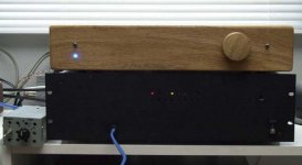
schro20 said:I have uploaded pictures (with some brief comments) to http://picasaweb.google.com/schro20/RevCCase
I used not electrical tape for some of the lead insulation but ordinary tape. Scouts honor, this will be fixed, but the evening I put this together (and couldn't possibly wait) I couldn't find my electrical tape. (That was the embarrassing part I alluded to in an earlier posting...)
Looks good!.
Nice idea mounting transformers on that metal profile!
You could have shorter cables reversing the order, back -> amps -> transformers -> front (you could do it simply swapping front and back plates), and placing backside the pot using a shaft.
This implies that PS cables go back to front but, at least in my setup that is deadly silent, this is not a problem.
An externally hosted image should be here but it was not working when we last tested it.
Ground loops can sound many different ways, and they are not "mains frequency" dependent.
Is yours a hum or his? A hum implies one tone / frequency, a hiss is generally more of white noise (broad spectrum), and the higher frequencies are usually more pronounced but the lower ones are there also.
Is yours a hum or his? A hum implies one tone / frequency, a hiss is generally more of white noise (broad spectrum), and the higher frequencies are usually more pronounced but the lower ones are there also.
pot noise
The thing is that when I turn the pot all the way to the right (effectively taking it out of the circuit and choosing maximum signal) I don't get any noise either. It's the middle position of the pot that gives me the most noise. To me this suggests an impedance problem.
Consider for argument's sake the source having 0 impedance and the sink having infinite impedance. Then the sink sees the two sections of the pot (to the left and right of the wiper) in parallel. At either extreme you have 0 impedance that the sink sees. But in the middle you have the highest impedance (2.5k in my case). So you get the most voltage drop for any noise insertion.
If I am not mistaken (I have no experience with this...) this suggests that the noise is injected due to impedance issues. So it seems that short of a buffer I can only help myself by better shielding. Or am I going awry in my argument here?
(More experiments will have to wait until tonight... Gotta attend to actual work... )
Peter
The thing is that when I turn the pot all the way to the right (effectively taking it out of the circuit and choosing maximum signal) I don't get any noise either. It's the middle position of the pot that gives me the most noise. To me this suggests an impedance problem.
Consider for argument's sake the source having 0 impedance and the sink having infinite impedance. Then the sink sees the two sections of the pot (to the left and right of the wiper) in parallel. At either extreme you have 0 impedance that the sink sees. But in the middle you have the highest impedance (2.5k in my case). So you get the most voltage drop for any noise insertion.
If I am not mistaken (I have no experience with this...) this suggests that the noise is injected due to impedance issues. So it seems that short of a buffer I can only help myself by better shielding. Or am I going awry in my argument here?
(More experiments will have to wait until tonight... Gotta attend to actual work...
)Peter
Its a sharp hum. Low frequency (not 60Hz though; presumably some multiple) and has a sharp edge to it. Hence my thinking that this is rectifier noise.troystg said:Ground loops can sound many different ways, and they are not "mains frequency" dependent.
Is yours a hum or his? A hum implies one tone / frequency, a hiss is generally more of white noise (broad spectrum), and the higher frequencies are usually more pronounced but the lower ones are there also.
peter
Peter,
Its the grounding of your pot. I think it doesnt make the noise when you turn it because you are helping to ground the pot better simply by holding onto it. But mostly I think its the wiring of the grounding of your pot. I had the same symptoms. Take a little wire from signal ground on the input to the board and run it back to the RCA ground and I think you will cure your problem.
Uriah
Peter-
Hum can be a tricky thing to get under control.
Your 'original' grounding system should be basically OK, though it certainly will not hurt to try a few quick re-arrangements of ground points. Perhaps by the time you read this you will have the problem solved.
Question: Is the 'tub' your toroids are sitting in made of steel, or aluminum?
It looks like the signal wires are running under the toroids enroute to the front of the chassis. I generally try to keep signal as far away from AC as possible. A pot at the back (as Clave suggests) would be good if you have all the hardware available. Otherwise, I'd consider running the signal wires tight to the edge of the case (ie square corners).
Also, tighter twisting of all the AC wiring cannot hurt. I know that some of the transformer wiring is very slippery/flexible so this can be tricky. Note that in Clave's amp he has heatshrink over the twisted AC feeds- if you hold the wires in place when you hit them with the heat gun you can get them to stay in place a bit better.
I'm sure you know the 'chopstick' technique for moving leads around- use a dry chopstick or plastic knitting needle to move leads around to see if you can locate the source of the problem.
You said the amp is dead quiet with shorted inputs. Do you have the hum problem when connected up to a (non-powered) source? Or only with the inputs 'open'?
BTW, in my cap switcher amp- I had a lot of hum problems which were caused by poor layout. I eventually had to move most of the amp/PS to a separate case from the switching relays and caps. So this sort of problem is quite common, especially if you are trying to make a fairly 'compact' unit.
Cheers
John
I am not certain of the nomenclature, but if I had to choose between the two terms I'd say it's a buzz.AndrewT said:is it a buzz rather than a hum?
Peter
When you get home, take the tape off of the pot terminals and re-photograph.
Also run a jumper between the ground terminals on the pot.
Fix the issue? Yes quit and enjoy. No, read on.
With the jumper still in place lift one of the shields at the RCA's.
Fix the issue? Yes quit and enjoy. No, read on.
Send it to me and I will dispose of it...
Also run a jumper between the ground terminals on the pot.
Fix the issue? Yes quit and enjoy. No, read on.
With the jumper still in place lift one of the shields at the RCA's.
Fix the issue? Yes quit and enjoy. No, read on.
Send it to me and I will dispose of it...
Cap switching box
Here are a few pics of the 'input cap switcher' that I put together. It's really more an electrical than electronic project- nothing very complicated or elegant but it works.
I can sit in my chair and switch cap choices in 'real time'. For me, this gets around some of the problems of 'adaptation' which have been discussed in the psychoacoustics field. It also helps if you deliberately don't memorize which caps are in each position, to get around some of the visual and price cues which could affect the results. That said, I don't have many very expensive caps in the collection, as you can probably see in the pics.
My initial plan was to put the myref amps in the same case, but ran into some hum problems, so opted to run the cap switcher in front of the (direct-coupled) amps, which are in their own case.
I used an eBay input switching relay board to select between 4 caps, and another relay from the parts box acts as a 'bank switcher' to allow 8 different (pairs) of caps to be compared.
No conclusions yet, but it does add to the fun when listening.
It's available for (short-term) loan to any local diyaudio members. Just drop me a line.
I'll attach a few pics.
Cheers
John
Attachments
Re: Cap switching box
Wow John!
this cap switcher is terrific!
If you haven't already did it, I would suggest you to keep one channel for DC coupling (the only true reference)
VictoriaGuy said:Here are a few pics of the 'input cap switcher' that I put together. It's really more an electrical than electronic project- nothing very complicated or elegant but it works.
I can sit in my chair and switch cap choices in 'real time'.
...
I used an eBay input switching relay board to select between 4 caps, and another relay from the parts box acts as a 'bank switcher' to allow 8 different (pairs) of caps to be compared.
No conclusions yet, but it does add to the fun when listening.
Wow John!
this cap switcher is terrific!
If you haven't already did it, I would suggest you to keep one channel for DC coupling (the only true reference)
Some others spaghetti...
I've put some caps burning-in...
I'm still waiting only Obbligatos
Uriah, can you see white MCAPs?
I've put some caps burning-in...
An externally hosted image should be here but it was not working when we last tested it.
I'm still waiting only Obbligatos
Uriah, can you see white MCAPs?
Andrew-AndrewT said:Hi,
will all that spaghetti and it's inductance change what passes through the caps?
Most of the 'spaghetti' you refer to, is power and relay switching wiring, I think.
Only one pair of caps is in circuit at a time.
The signal path is only increased by perhaps 30-40 cm. , compared to 'straight in' to the amp. Do you think that 30 cm of relatively straight conductor has an inductance whose effect you can hear? (a la gainclone concept..)
John
Re: Re: Cap switching box
Good idea- I'll free up a slot for a straight wire.
Of course, the whole device may actually be a trick already, with the caps and relays just an elaborate ruse to confuse 'golden eared' folks!
Cheers
John
ClaveFremen said:
If you haven't already did it, I would suggest you to keep one channel for DC coupling (the only true reference)
Good idea- I'll free up a slot for a straight wire.
Of course, the whole device may actually be a trick already, with the caps and relays just an elaborate ruse to confuse 'golden eared' folks!
Cheers
John
- Home
- Amplifiers
- Chip Amps
- The new "My Ref" Rev C thread