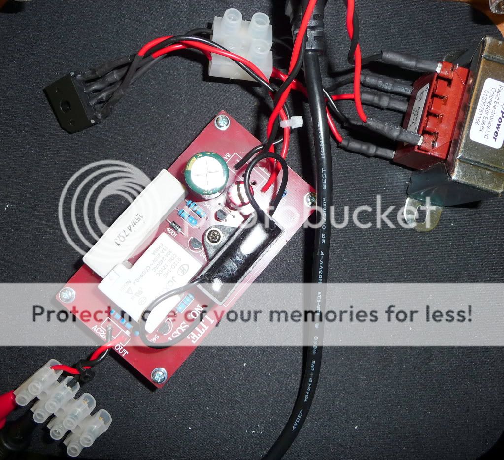
The relay coil is rated with 0,9 W at 12 V, hence draws 75 mA. 240 V x 75 mA = 18 W plus the consumption of the rest of the control circuit. It seems the manufacturer relies on the 1µ5 capacitor to dissipate most of the waste heat. Pretty scary in view of everybody striving for energy efficiency.
Richard, would you publish the manufacturer's name, so that everybody can avoid buying from him?
Hi David
I'm not sure its fair to give the name of the vendor as they maybe unaware of this. I wouldn't want it to affect the sales of their other products. The vendors been quite helpful so far.
The manufacture is LITE Audio
Regards
Last edited:
Hi Richard, thanks for the Christmas brain teaserI have no idea what the answer is
I tried the voltdrop part of the cct and voltage was reduced to 6V ac, lightbulb tester glowed (60W bulb) and the cct drew 20VA.
Thanks for trying Barry
I can't find any proof of your assumption in that link.No, the reactive feed is non-dissipative. See EDN PDF for more information.
Theory in the form of Kirchhoff's Current Law predicts a power consumption of > 18 W. audio1st measured a consumption of 20 VA in practice. The relay consumes only 0,9 W, which leaves most of the power to be dissipated. The 1µ5 capacitor is the only device, where that can happen due to its function in the circuit (voltage divider) and due to its physical size.
Quoted from the article:
Direct rectification normally
gives a voltage approaching
the peak value of
the mains voltage, but placing
an impedance in series
with the ac input reduces
the dc output voltage. If the
impedance is resistive, low efficiency results. However, if the
impedance is reactive, the circuit is essentially lossless,
except for diode losses and a small power loss in the parasitic
series resistance.
I don't know how much more plain it could be...
I can't find any proof of your assumption in that link.
Theory in the form of Kirchhoff's Current Law predicts a power consumption of > 18 W. audio1st measured a consumption of 20 VA in practice. The relay consumes only 0,9 W, which leaves most of the power to be dissipated. The 1µ5 capacitor is the only device, where that can happen due to its function in the circuit (voltage divider) and due to its physical size.
Hi David, my test was carried out with a 47r load resistor because I did not no the value of the resistor that parallels the coil resistance.
Barry.
"Essentially lossless" is not a plain explanation. It is a statement that becomes absurd, when you read later on in the text
That is pretty similar to the statements of CFL aka "energy-saving lamp" manufacturers that tell you their lamps only consume 20 W, but 'forget' to tell you that their power factor of ~0,5 makes it necessary to produce 40 VA of apparent power in a power plant to make the lamps measure as consuming 20 W of real power.
audio1st measured a consumption of 20 VA to activate a 0,9 W relay coil. The difference must go somewhere. That is plain to me.
the power factor is approximately 12/(230X1.14)=0.045.
That is pretty similar to the statements of CFL aka "energy-saving lamp" manufacturers that tell you their lamps only consume 20 W, but 'forget' to tell you that their power factor of ~0,5 makes it necessary to produce 40 VA of apparent power in a power plant to make the lamps measure as consuming 20 W of real power.
audio1st measured a consumption of 20 VA to activate a 0,9 W relay coil. The difference must go somewhere. That is plain to me.
Hi David, my test was carried out with a 47r load resistor because I did not no the value of the resistor that parallels the coil resistance.
A 12 V 0,9 W coil corresponds to 160 Ohms. The difference is not too big. When you simulate it in LTSpice, you get a total power consumption of 18 W, just as Kirchhoff's law predicts.
David
Tested with 160 ohm load, figures are, 20VA, 2W and .08 power factor.
DC voltage across load now 15V, was 5V with 47ohm load.
The resistor I thought was parallel to the coil is only connected before the relay is powered, I guess 150ohms, this keeps the load and voltage constant.
Barry.
DC voltage across load now 15V, was 5V with 47ohm load.
The resistor I thought was parallel to the coil is only connected before the relay is powered, I guess 150ohms, this keeps the load and voltage constant.
Barry.
Such a capacitive load will in theory improve (= increase) the power factor, if you operate inductive consumers like CFLs, SMPSs or inductive motors in your household at the same time. The better the power factor, the more of the apparent power turns into real power and the more of it will be measured by the electricity counter.If we take current through a series connected capacitor to our circuit (soft start control), do we raise the power/load factor of our total household demand?
The trick of a bad power factor is that we as consumers don't have to pay for the reactive part. That is also part of the swindle with CFLs. The energy counters that are still in use only measure real power. That is why your electricity supplier obliges you to compensate for reactive loads. E. g. here in Germany you can use up to 130 VA of reactive loads per phase without compensation. Once you pass that figure, you need to compensate to a power factor within -0,95 and +0,95.
In the near future we will all get electronic counters that can measure apparent power and calculate power factors. That means, we won't need to buy compensation plants, but will then have to pay for the apparent power and probably an additional fee for extremely bad power factors, too.
The apparent power is, what needs to be generated and what leads to heat dissipation across any impedance. This became obvious in Tripmaster's light bulb tester and in audio1st's measurements. If you work with reactive loads, all components have to be calculated to withstand the apparent current, not the lower real current. E. g. if you connected that soft-start module to a transformer with a 240 V secondary, you could not use a 2 VA transformer and think: "Hey, I have more than 100 % spare for that 0,9 W relay coil." The transformer would be loaded with 20 VA. Cables, rectifiers, wires, everything needs to be made for 20 VA, even if the electricity counter only shows 2 W of average consumption.
Hi
Ive been hunting around for a replacement soft-start circuit and wondered if anyone can provide helpful opinions based on the following kits/circuits? It appears most of the kits run directly from the mains and not via a separate DC power supply.
http://avondaleaudio.com/diy-audio/soft-start-module/
Avondale supplies the PCB and relays for about £10, they also supply a pre-built board but I would rather build it it myself and save money. I will need to source the other components separately. The company is UK based.
Ska Audio SoftStart
Connexelectronic
Soft-Start Circuit For Power Amps
L C Audio Technology / Soft Start
sjostromaudio.com - SST01 Softstart for toroid transformers
Thanks
I'll be buying the one from Connexelectronic shortly. Of all the soft starts I've seen available, it's the best looking one at a good price. It has it's own transformer, uses thermistors, has an actual timer for the relay and has a remote input if you want to set up remote power toggling.
Hi Richard,
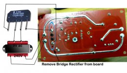
I think you could just remove the rectifier from the soft start board and use it with a small 9V transformer?
Barry
Thanks Barry
I'll have a go at this before purchasing another soft-start
give us a clue.
For the soft start alone or to power the Queen Mary.
Just the soft start as per Audio1st previous post
Hi Richard,
I think you could just remove the rectifier from the soft start board and use it with a small 9V transformer?
Barry
Hi Barry
I removed the rectifier from the soft-start board tonight and connected a 9VAC transformer, wired in parallel so as to power the soft-start separately. I then connected the AC supply from the IEC mains inlet to the s-s board and 9V transformer. The relay clicks as per normal, and I am getting 233V on the s-s output. After cutting the power I touched the 47R power resistor and it felt warm.
The bulb tester doesn't glow, like it did before the mod
Is there anything else I can do to check the s-s is working correctly?
Thanks for the practical tip!
- Home
- Amplifiers
- Chip Amps
- Chip amp power supply- a beginners guide