Capacitor across power switch
Hi,
In post #44 of this thread the question was asked:
I couldn't find an answer to this one yet and am very interested.
Any explanation or comments would be greatly appreciated!
Thanks,
Joe
Hi,
In post #44 of this thread the question was asked:
2) You say "Place a small Class X1 rated capacitor (around 0.1 uF /275 volts is fine) across the switch contacts. "... how does that not short the switch given that we're switching AC (which a cap does not block, correct?)
I couldn't find an answer to this one yet and am very interested.
Any explanation or comments would be greatly appreciated!
Thanks,
Joe
I've never noticed two caps across a 2pole mains switch....and if you are switching both active and neutral do you place a capacitor across both poles of the switch?
I'm waiting for the answer.

what is currently discussed...??
Hi everyone!
I'm very interested in this topic - PSU, UPS, SMPS... - and I have long experinece of building them for audio applications, lab-supplies(I use ±V for all my amp-designs, pre-, pwr-amp's - u get rid of the big bulky cap, and some distortion. - so I designed a dual, regulated PSU(linear), Volt adj. from 0 to ±60V and ampere adj from ±100mA to ±3A, and of course a LED display for monitoring Voltage and Ampere ). It's a very hot topic - chip amp psu - since it's over fifty pages.... and I'm too lazy to read them all from one to 54...
But I saw that "soft-starters", "unregulated psu", and one regulated w/ LM317/337(max current handling is 1.5A, with BIG coolers).
I though I might be of some assistant... since it's "chip amp's", we're dealing with class-B amps, and then it becomes a bit trickier to design a reg. PSU, hence the amp want draw any current as long as there's no input signal..
And if the input goes from zero to line-level(.775V r.m.s.) in 1µ second, the supply which has been "asleep" needs to respond equally fast, then you need something that can deliver 2 or 3 Amp(or whatever the max effect/current the amp has...).. and I've destroyed many buffered(you 'beef' up the current handle with a transistor or a FET) LM317/337 and 78xx circuits, with 10 000µF cap's on each rails output, a 10mF@35 - 40V holds lots of current that will destroy a simple 1N4001 diode, you need to protect everything in the power circuit(even unregulated should have diodes on the output, an accident can happen easy, and it's better that a fuse blows, than the cap's or the rectifier takes the 'blow', if u happen to short-circuit the supply...).. anyway, I would like to follow this thread, help out if I can.... meanwhile checkout Rod Elliots Soud Page , you'll find much info 'bout linear and switched power supply.. and much more, start with "articles", I saw that some else had already refereed to his site, with one of his projects "soft start" for speaker(s).. I've checked out some of the links and read parts of this thread, and a soft-starter is very simple to build your self!
I use 4*47R/10W in parallel, and a zener equal to the relay voltage, and a trimmer+a fixed resistor and a cap about 100µ, a diode(1N4148), and a BC547 or similar(depends on how many relays you'll use, and the BJT SOA), and as the voltage rises to zener-voltage, say 12DC, the emitter voltage will be high enough to pull the relay - the relay coil should be fitted between the EMITTER and ground - emitter-voltage is equal to the base voltage, if you use a NPN BJT. And most relays needs only 50mA for "on-state"...
Power Supplies, whatever the "flavor", is one of the main part of the amplifier, to get a good result. A poorly designed PSU will introduce "hum", it will "dipp" if your amp craves more power than the supply can deliver, then the base will start to sound distorted etcetera...
Here's some real good articles....(you need to be well versed in math though )
Hi everyone!
I'm very interested in this topic - PSU, UPS, SMPS... - and I have long experinece of building them for audio applications, lab-supplies(I use ±V for all my amp-designs, pre-, pwr-amp's - u get rid of the big bulky cap, and some distortion. - so I designed a dual, regulated PSU(linear), Volt adj. from 0 to ±60V and ampere adj from ±100mA to ±3A, and of course a LED display for monitoring Voltage and Ampere
). It's a very hot topic - chip amp psu - since it's over fifty pages.... and I'm too lazy to read them all from one to 54...But I saw that "soft-starters", "unregulated psu", and one regulated w/ LM317/337(max current handling is 1.5A, with BIG coolers).
I though I might be of some assistant... since it's "chip amp's", we're dealing with class-B amps, and then it becomes a bit trickier to design a reg. PSU, hence the amp want draw any current as long as there's no input signal..
And if the input goes from zero to line-level(.775V r.m.s.) in 1µ second, the supply which has been "asleep" needs to respond equally fast, then you need something that can deliver 2 or 3 Amp(or whatever the max effect/current the amp has...).. and I've destroyed many buffered(you 'beef' up the current handle with a transistor or a FET) LM317/337 and 78xx circuits, with 10 000µF cap's on each rails output, a 10mF@35 - 40V holds lots of current that will destroy a simple 1N4001 diode, you need to protect everything in the power circuit(even unregulated should have diodes on the output, an accident can happen easy, and it's better that a fuse blows, than the cap's or the rectifier takes the 'blow', if u happen to short-circuit the supply...).. anyway, I would like to follow this thread, help out if I can.... meanwhile checkout Rod Elliots Soud Page , you'll find much info 'bout linear and switched power supply.. and much more, start with "articles", I saw that some else had already refereed to his site, with one of his projects "soft start" for speaker(s).. I've checked out some of the links and read parts of this thread, and a soft-starter is very simple to build your self!
I use 4*47R/10W in parallel, and a zener equal to the relay voltage, and a trimmer+a fixed resistor and a cap about 100µ, a diode(1N4148), and a BC547 or similar(depends on how many relays you'll use, and the BJT SOA), and as the voltage rises to zener-voltage, say 12DC, the emitter voltage will be high enough to pull the relay - the relay coil should be fitted between the EMITTER and ground - emitter-voltage is equal to the base voltage, if you use a NPN BJT. And most relays needs only 50mA for "on-state"...
Power Supplies, whatever the "flavor", is one of the main part of the amplifier, to get a good result. A poorly designed PSU will introduce "hum", it will "dipp" if your amp craves more power than the supply can deliver, then the base will start to sound distorted etcetera...
Here's some real good articles....(you need to be well versed in math though
)
Last edited:
... the supply which has been "asleep" needs to respond equally fast, then you need something that can deliver 2 or 3 Amp(or whatever the max effect/current the amp has...).. lots of current that will destroy a simple 1N4001 diode, you need to protect everything in the power circuit(even unregulated should have diodes on the output,
Why would you use 1N4001 (which is 1 amp rated) when building a PSU capable of 2 or 3 amps? Diodes are cheap and readily available in higher current capacities.
I have never found a need for diodes on the output though, if you have an active component that doesn't like higher output voltage than input, you can simply place a diode reversed across the power leads of that component so that the forward voltage drop of the diode is the highest reverse voltage the component will see... although more elaborate ICs may already have this protection built-in.
! : " Why would you use 1N4001 (which is 1 amp rated) when building a PSU capable of 2 or 3 amps? Diodes are cheap and readily available in higher current capacities. ..."
So cheap in fact, one should seek out the "fast recovery" type diodes = better response = better noise figures.
Also the 1N4001 is functionally equal to 1N4002, 1N4003 ... spec sheet: 1N4001 thru 1N4007 ...
Of interest: Schottky Barrier Diodes = very fast and not all that expensive. (This one comes in a "4-pack" as a ready to use full wave diode bridge )
----
pacificblue: " You use a single C or RC across the [switch or] switched side. ..."
DC only! ... switching an AC load across a cap may produce interesting or peculiar results, depending on frequency and power and load resistance ... like oscillations or passing the AC component of the signal right through to the working load. This is where the "start up thump" sometimes originates in some power amps ...
So cheap in fact, one should seek out the "fast recovery" type diodes = better response = better noise figures.
Also the 1N4001 is functionally equal to 1N4002, 1N4003 ... spec sheet: 1N4001 thru 1N4007 ...
Of interest: Schottky Barrier Diodes = very fast and not all that expensive. (This one comes in a "4-pack" as a ready to use full wave diode bridge
)----
pacificblue: " You use a single C or RC across the [switch or] switched side. ..."
DC only! ... switching an AC load across a cap may produce interesting or peculiar results, depending on frequency and power and load resistance ... like oscillations or passing the AC component of the signal right through to the working load. This is where the "start up thump" sometimes originates in some power amps ...
Last edited:
Stop! I only used 1N4001 as an example, since everybody knows that one... of course you need diodes that can hadle the power... I use 1N5408 in preamp-supplies, and then the "short circuit" current is about .5A... and TO-220's with heat sink in power amp supplies, with current peaks about 50A...... So pretty please... don't get hanged up on trivia! What I meant got lost, when you criticise the "example" diode! And 1N4001 can handle about 5 amps for a short time, so if you use fast blow fuses, then the fuse will blow before the diode... And if maximum current is rated at 10A, of toroid transformer(or E-shaped, C-transformer or what ever transformer you want to use, is that clear enough..??), then you need a 16A diode, and 10A fb fuse.. I though that was obvious .....
I only used 1N4001 as an example ... I use 1N5408 in preamp-supplies, and then the "short circuit" current is about .5A...
Moi Bueno
Hi !
I have a question regarding a power supply kit bought on eBay.
Components on the board : 10000uF NOVER capacitors, 0.1uF WIMA capacitors, 4.7K resistors, 35A rectifier bridge.
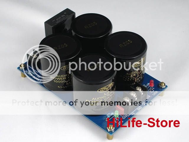
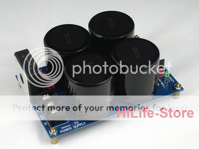
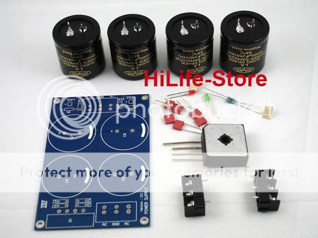
I have a toroidal transformer with dual 24v secondaries ( 4 wires ) ... as you can see in the pictures above there are 3 "pins" for the input labeled AC-GND-AC. How should I connect the wires from the transformer ?. It's part of a LM3886 Kit.
I have a question regarding a power supply kit bought on eBay.
Components on the board : 10000uF NOVER capacitors, 0.1uF WIMA capacitors, 4.7K resistors, 35A rectifier bridge.
I have a toroidal transformer with dual 24v secondaries ( 4 wires ) ... as you can see in the pictures above there are 3 "pins" for the input labeled AC-GND-AC. How should I connect the wires from the transformer ?
. It's part of a LM3886 Kit.
Last edited:
Hi,
build a mains light bulb tester.
Use it to power up the transformer.
It will help stop you injuring yourself and help avoid destruction of your transformer/project.
you need to join two of the secondary wires.
From this junction you run a wire to the central GND pad.
The other two secondaries go to the AC pads.
Do this wrong and you risk an accident.
Do take precautions to avoid damage.
Last edited:
Nuuk- the regulated power supply links on your website page having to do with power supplies are not working. Pedja took his pages down.
this one- http://www.pedjarogic.com/gc/supplies.htm and the related ones.
this one- http://www.pedjarogic.com/gc/supplies.htm and the related ones.
Nuuk- the regulated power supply links on your website page having to do with power supplies are not working. Pedja took his pages down.
this one- http://www.pedjarogic.com/gc/supplies.htm and the related ones.
Did you mean this page?
Pedja Rogic Audio Pages - Chip Based Power Amp i.e. Gainclone - Regulated Supplies
Nuuk's page-
Building a Gainclone chip amp power supply.
has this paragraph-
I wasn't too keen on the LM338 regulated GC but I love (and still use) the discrete regulated version designed by Pedja Rogic. If you would like to try the >>discrete regulated power supply<< but don't have the confidence to build your own on stripboard, the good news is that you can now buy either PCB's, or completed modules from Pedja. See >>here<< for details.
the links are broken.
first link
http://www.pedjarogic.com/gc/supplies.htm
2nd link
http://www.audialonline.com/diy/moduler/
probably the same as the one you link to? Anyway, the links are dead and I wanted to tell Nuuk about it.
Sorry, I forgot that link was still there. Unfortunately (but perhaps understandably) Pedja has dropped all his DIY stuff to concentrate on his commercial sales. He did let me know but I forgot that I had that link still on the site.
I have now updated the site but please be aware that I am only updating the 'new' site these day. So that page is now at:
Building a Gainclone chip amp power supply.
Please bookmark the new URL.
I have now updated the site but please be aware that I am only updating the 'new' site these day. So that page is now at:
Building a Gainclone chip amp power supply.
Please bookmark the new URL.
Bi-amping 5 channels with 10 GC amps
Hello,
Just a few questions if anyone has suggestions or starting points, as I am new to designing my own amplifiers. My goal is to bi-amp 5 separate MTM speakers that I just finished building for a total of 10 amplifiers. I will be using the LM3886 chip. The crossover frequency is 2.5kHz. The woofers are 8 ohm 88dB 35 watts each and the tweeters are 6 ohm 92dB 40 watts each.
First question - Would there be any benefit to run the woofers in series for 16ohm load instead of parallel to 4ohms? Obviously there would be less overall output power, less current through the chip, but the damping should improve. Does anyone know the appropriate power supply voltage for this impedance?
Second question - Since I am bi-amping, effectively using two amplifiers in place of one, would the two amps require the same power as one amplifying the full range? Can I obtain more power from each amp with the narrower bandwidth?
Lastly, question three - Any ideas for the size of the power transformer for such a system? If I do go with a higher DC voltage for running the woofers at 16ohm, should I use separate transformers for high and low frequency? I plan on using separate supply boards for each amp as it is.
I did do research, but not many people have created a ten channel GC.
I appreciate any and all help!
if you want to power multiple amplifiers in a single box then it is far easier if all can run from the same voltage.
Can your drivers be set to the same sensitivity?
I think they can (maybe).
Design for +-28Vdc from a 22+22Vac transformer. This can power a chip whether it's connected to a 4ohm, or 6ohm, or 8ohm, or 4 to 8ohm speaker.
The drivers are:
The resulting sensitivity is 88dB/2.83V @ 1m + ~6dB = ~94dB/2.83V @ 1m. Well quite a bit less because the amplifier cannot double it's power when the load is reduced from 8ohm to 4ohm. Subtract between 0.5dB and 1.5dB, if using one chip to drive the parallel load.
The treble is 92dB/W @ 1m.
1W into 6ohm is equivalent to 2.45V.
The sensitivity in volts is 92dB/2.45V @ 1m.
Rescale this for a 2.83Vac drive voltage and you get an extra 1.25dB.
The resulting voltage sensitivity is ~93.3dB/2.83V @ 1m.
Not quite the same as the woofer but pretty close. However, check the specifications of the drivers. Are the sensitivities quoted for 1W or 2.83V, it makes a difference.
Why limit your chipamps to 4ohm loading by paralleling the woofers? I would dedicate a chipamp to every driver. Now you can design for 6ohm loading and using a 24Vac transformer. If you use an active high pass filter as part of the treble crossover then you can probably get away with treating the treble driver as if it were an 8ohm load and go to a 25Vac or 26Vac transformer.
Finally, where are your speakers?
Are they spread around the room?
How do you intend to cable from a 10channel amplifier to all these distributed speakers/drivers.
Put each speaker amplifier right next to the speaker terminals. This remote amplifier can be a two channel or three channel device to suit the speaker it is driving. Speaker cables are very short. Speaker cable effect on amplifier stability is much reduced. Speaker cable cost is much reduced.
Line level twisted pair are much cheaper and much smaller to run to remote amplifiers.
Can your drivers be set to the same sensitivity?
I think they can (maybe).
Design for +-28Vdc from a 22+22Vac transformer. This can power a chip whether it's connected to a 4ohm, or 6ohm, or 8ohm, or 4 to 8ohm speaker.
The drivers are:
Two woofers in parallel from one chipamp present a 4ohm load.The woofers are 8 ohm 88dB 35 watts each and the tweeters are 6 ohm 92dB 40 watts each.
The resulting sensitivity is 88dB/2.83V @ 1m + ~6dB = ~94dB/2.83V @ 1m. Well quite a bit less because the amplifier cannot double it's power when the load is reduced from 8ohm to 4ohm. Subtract between 0.5dB and 1.5dB, if using one chip to drive the parallel load.
The treble is 92dB/W @ 1m.
1W into 6ohm is equivalent to 2.45V.
The sensitivity in volts is 92dB/2.45V @ 1m.
Rescale this for a 2.83Vac drive voltage and you get an extra 1.25dB.
The resulting voltage sensitivity is ~93.3dB/2.83V @ 1m.
Not quite the same as the woofer but pretty close. However, check the specifications of the drivers. Are the sensitivities quoted for 1W or 2.83V, it makes a difference.
Why limit your chipamps to 4ohm loading by paralleling the woofers? I would dedicate a chipamp to every driver. Now you can design for 6ohm loading and using a 24Vac transformer. If you use an active high pass filter as part of the treble crossover then you can probably get away with treating the treble driver as if it were an 8ohm load and go to a 25Vac or 26Vac transformer.
Finally, where are your speakers?
Are they spread around the room?
How do you intend to cable from a 10channel amplifier to all these distributed speakers/drivers.
Put each speaker amplifier right next to the speaker terminals. This remote amplifier can be a two channel or three channel device to suit the speaker it is driving. Speaker cables are very short. Speaker cable effect on amplifier stability is much reduced. Speaker cable cost is much reduced.
Line level twisted pair are much cheaper and much smaller to run to remote amplifiers.
Last edited:
Thanks for the prompt response!
Ok, I've settled on the +-28vdc for both High and Low frequency amplifiers. I'm not too worried about matching the sensitivities because I can dial it in with the crossovers and an SPL meter.
You mentioned about having a separate amp for each woofer. Well, that would mean 15 amplifiers... A goal I'd like to work towards, but not yet. (Lack of funds...)
You also mentioned placing the amps near the speakers. I had looked into each speaker having a plate amp. Solen has a two-way plate amp with a built in crossover. I like the idea, but not enough to cut a big square out of the back of the speaker. I wouldn't have to use a plate for my design, though. However, I would need a 110 receptacle and a separate power transformer at each speaker. I'm fairly certain that my apartment has bad grounding, ground loops might be an issue. Speaker cable cost is greatly reduced, but now we need 5 transformers. I agree that this is the ideal solution, but not at the moment. With the modular format, these goals would be reached fairly easily down the road. (When there's more cash on hand )
For the time being, I would like to put the amplifiers in one case but I'm at a loss for what size transformer would be adequate to power all 10 amplifiers. Any ideas?
5 Mid/bass amplifiers and 5 Treble amplifiers from one transformer will never deliver 10*60W to your loads. Unless you were to accidentally send a Big DC pulse into the amps.
I assume the first amp needs 1.5*W as VA then the other 4 need 1*W as VA. Here I think it would be reasonable to assume that all 5 Treble amps need 0.5*W as VA.
That comes to a total of 480VA. That I reckon allows the amplifiers to think they are each being powered by a 90VA portion of the PSU. The range for economic transformers is 1 to 2times Watts for VA.
In this 10 amplifier case that becomes 320 to 640VA transformer.
You can use a 300VA transformer and the amps will perform pretty well. you can get small increases in performance as you move towards 600VA and not cost a lot of extra cash. Beyond 600VA the value for money in terms of performance per $ is going to get worse.
The amps will work with any 22+22Vac transformer between 200VA and 1000VA. You choose.
Last edited:
- Home
- Amplifiers
- Chip Amps
- Chip amp power supply- a beginners guide