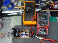
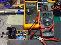
audio1st said:Hi Richard,
-V readings look OK, you may want to try a different zener (closer to 27v) 28.3 is 5% error.
+V has a problem with your input voltage (28.7v) is low, is the problem on the rectifier board or is it the bleeder resistor?
Scrub that, you may have measured the wrong point? If you measure across the +V input and get near 35v everything is fine!
PS, did you swap the 130r and the 1k on the V+side?
I am using the same rectifier to test each side. I will use separate rectifiers when both + & - supplies are running simultaneously
Yes I swapped the resistors over
I'm just going to remeasure the v+ side
Hi Richard,
The point of the readings was to find the voltage across each component.
V-
A is V across zener (28.2)
Difference between A, B is V across J-Fet (5.9)
Difference between B, C is V across 130r, (1.2)
V+
A is V across zener (27.5)
Difference between A, B is V across 130r, (1.2)
Difference between B, and total V, is V across J-Fet, ( 6.5)
Current across 130r is (ohms law), 1.2/130 =9.2mA.
I should avoid the maths, I'm bound to get pulled up on it
Barry.
The point of the readings was to find the voltage across each component.
V-
A is V across zener (28.2)
Difference between A, B is V across J-Fet (5.9)
Difference between B, C is V across 130r, (1.2)
V+
A is V across zener (27.5)
Difference between A, B is V across 130r, (1.2)
Difference between B, and total V, is V across J-Fet, ( 6.5)
Current across 130r is (ohms law), 1.2/130 =9.2mA.
I should avoid the maths, I'm bound to get pulled up on it

Barry.
Hi
I have finally built the second power supply and have also change the zener on the -V of the first.
Would you mind casting your eyes across these figures?
Thanks
Richard
First Power Supply with -V Zener replaced
-V
'A' -28v
'B' -33.4v
'C' -34.5v
Output -25.8v
Voltage across JFet -5.4v
Voltage across 130R -1.1v
Current across 130R 8.5mA
+V
'A' +27.6v
'B' +28.6v
'C' +28.6v
Output +25.5v
Voltage across 130R +1v
Voltage across JFet +3.1v
Current across 130R 7.7mA
Second Power Supply
-V
'A' -27.8v
'B' -33.8v
'C' -34.8v
Output -25.6v
Voltage across JFet -6v
Voltage across 130R -1v
Current across 130R 7.7mA
+V
'A' +27.8v
'B' +29.1v
'C' +29.1v
Output +25.9v
Voltage across 130R +1.3v
Voltage across JFet +3.2v
Current across 130R 10mA
AndrewT said:why do you show the B & C voltages the same on the +ve supply and yet you calculate the voltage drop as 1.0V or 1.3V?
Thanks for pointing out my mistake!

First Power Supply with -V Zener replaced
-V
'A' -28v
'B' -33.4v
'C' -34.5v
Output -25.8v
Voltage across JFet -5.4v
Voltage across 130R -1.1v
Current across 130R 8.5mA
+V
'A' +27.6v
'B' +28.6v
+34.5v (Total voltage taken from drain pin of J309)
Output +25.5v
Voltage across 130R +1.0v
Voltage across JFet +5.9v
Current across 130R 7.7mA
Second Power Supply
-V
'A' -27.8v
'B' -33.8v
'C' -34.8v
Output -25.6v
Voltage across JFet -6v
Voltage across 130R -1v
Current across 130R 7.7mA
+V
'A' +27.7v
'B' +29.0v
+34.3v (Total voltage taken from drain pin of J309)
Output +25.9v
Voltage across 130R +1.3v
Voltage across JFet +5.3v
Current across 130R 10mA
Hi Richard,
Your results all seem fine, as long as the output voltage is close to being equal for all rails, you have correctly made the circuits..
I have been trying to get a closer match of rail voltages without critical zener matching.
So I added a trimmer to each side and can now match voltages, I tested it on LTspice and found no abnormal readings.

Attachments
audio1st said:Hi Richard,
Your results all seem fine, as long as the output voltage is close to being equal for all rails, you have correctly made the circuits..
I have been trying to get a closer match of rail voltages without critical zener matching.
So I added a trimmer to each side and can now match voltages, I tested it on LTspice and found no abnormal readings.
Hi Barry
Thanks for letting me know
What value trimmer did you use on your board?
Richard
audio1st said:Output voltages without trimmers..
If you're having problems, I'm happy to help

Nuuk said:When you two are quite ready, there is the small matter of how you like the sound with the regulated supply! If you wait much longer you will need to replace those lytics!


Puffin said:I love a happy ending
I think its been frustrating for eveyone...but me
was this Q ever answered?Redshift187 said:Just in time for me too as I'm starting my PSU today or tomorrow.
The only thing that didn't make sense is use of the lightbulb protection... specifically, wouldn't you test with the 40W, then the 60W, then the 100W, THEN use the bulb bypass switch?
Start with the lowest power of bulb.
If it goes off after the initial flash then all is probably OK. Check some voltages to confirm correct operation.
If it glows slightly, check the voltage entering the transformer. If this is >95% of mains voltage AND the circuit voltages are all OK, then operate the bypass switch without going to a higher wattage bulb.
If the low wattage bulb is causing a significant voltage drop on the mains side AND the checked voltages are OK, then change to a higher rated bulb and recheck operating voltages. If OK then operate bypass switch.
The only need for higher wattage bulbs is to suit amps that dissipate a higher quiescent power.
An amp that is biased to 10mA from +- 28Vdc is only half a watt + transformer loss.
An amp that is biased to 200mA from +-50Vdc is 20W + transformer loss. A different load that will requires a different bulb. Start low to be safe, it does no harm.
The one exception is to a soft start resistor. This must not stay in circuit if the input voltage is too low. It will overheat if a low voltage is fed to the primary.
- Home
- Amplifiers
- Chip Amps
- Chip amp power supply- a beginners guide

