Hi Richard,
Yes both zeners face the same way. I think my problem is I didn't have any J309 and I have used a different N-Fet. I will have to order some..I managed to get all the transistors from Maplins.
It looks as if your centre pin on the J309 goes to the 1k resistor?
Yes both zeners face the same way. I think my problem is I didn't have any J309 and I have used a different N-Fet. I will have to order some..I managed to get all the transistors from Maplins.
It looks as if your centre pin on the J309 goes to the 1k resistor?
audio1st said:Hi Richard,
Yes both zeners face the same way. I think my problem is I didn't have any J309 and I have used a different N-Fet. I will have to order some..I managed to get all the transistors from Maplins.
It looks as if your centre pin on the J309 goes to the 1k resistor?
Yes my 1k resistor goes to the centre pin (source) of the J309
Got it sorted, V- so far, forgot to connect the reservoir cap. Stable now..
25v transformer, with 27v Zener ends up with -25vDC after all the regulation.
26.5v across Zener.
11v across Fet
0.8v across R2.
FET connections, G to 1k, D to Zener and S to 130r...
25v transformer, with 27v Zener ends up with -25vDC after all the regulation.
26.5v across Zener.
11v across Fet
0.8v across R2.
FET connections, G to 1k, D to Zener and S to 130r...
Attachments
audio1st said:Got it sorted, V- so far, forgot to connect the reservoir cap. Stable now..
25v transformer, with 27v Zener ends up with -25vDC after all the regulation.
26.5v across Zener.
11v across Fet
0.8v across R2.
FET connections, G to 1k, D to Zener and S to 130r...
Audio1st! Its a marathon not a sprint

So is the schematic wrong, or am I misreading it?
Well done BTW
Hi Richard,
Schematic is right, I have used a different Fet, opposite pin out to the J309, makes no difference as long as you follow the correct G,D,S connections.
You may have damaged your J309, but you might as well swap the 130r and the 1k with each other and see if it helps?. My zeners are 1.3W from Maplin. Have you installed a new Zener yet?
audio1st said:Hi Richard,
Schematic is right, I have used a different Fet, opposite pin out to the J309, makes no difference as long as you follow the correct G,D,S connections.
You may have damaged your J309, but you might as well swap the 130r and the 1k with each other and see if it helps?. My zeners are 1.3W from Maplin. Have you installed a new Zener yet?
I'm just about to

I have replaced the Zener, J309 and R2 resistor
For the purpose of this test I have kept R2 (130R) connected to the Gate, Drain is connected to Zener and Source to 1K.
Here are the readings...
Across R2 (130R) =34.8v
Across Zener=27v
Gate (Connected to R2)=34.8v
Source (Connected to 1K) =33.1v
Drain (Connected to Zener) =27v
Output 24.9v
The light bulb illuminates for a second and goes out immediately. Before the component swap the filament in the bulb would flicker dimly whilst the on button remained pressed
If some of these readings are too high I will swap the 1K and R2 resistors around.
For the purpose of this test I have kept R2 (130R) connected to the Gate, Drain is connected to Zener and Source to 1K.
An externally hosted image should be here but it was not working when we last tested it.
Here are the readings...
Across R2 (130R) =34.8v
Across Zener=27v
Gate (Connected to R2)=34.8v
Source (Connected to 1K) =33.1v
Drain (Connected to Zener) =27v
Output 24.9v
The light bulb illuminates for a second and goes out immediately. Before the component swap the filament in the bulb would flicker dimly whilst the on button remained pressed
If some of these readings are too high I will swap the 1K and R2 resistors around.

I have swapped the two resistors around so the R2 is 1k and the resistor before it is 130R
The voltages are now...
Across R2 (1K) =34.5v
Across Zener (27v) =28.1v
Gate=34.3v
Source=33.3v
Drain=28.3v
Output 25.8v
The output voltages have increased and the voltage is still to high across R2.
I will check again for shorts
The voltages are now...
Across R2 (1K) =34.5v
Across Zener (27v) =28.1v
Gate=34.3v
Source=33.3v
Drain=28.3v
Output 25.8v
The output voltages have increased and the voltage is still to high across R2.
I will check again for shorts
audio1st said:Hi Richard,
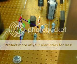
I still don't know where you are taking your readings from so, can you please give me the DC readings from the points in the picture.
I’m in the office at the moment but I will provide these readings later this afternoon
I’ve been taking the ground connection from the output end of the board.
Everyone going to breathe a sigh of relief when this is sorted!

Hi Richard,
If you connect the neg probe to Gnd and use the pos probe to take readings, they should all be -V readings.
When you say across R2 and across zener, 34V and 28V, these items are in series across the supply and would mean you had a supply V of at least 62V?
If you measured R2 to Gnd and got -35V, this means that if your supply is about -36V then only 1V across R2...
audio1st said:Hi Richard,
If you connect the neg probe to Gnd and use the pos probe to take readings, they should all be -V readings.
When you say across R2 and across zener, 34V and 28V, these items are in series across the supply and would mean you had a supply V of at least 62V?
If you measured R2 to Gnd and got -35V, this means that if your supply is about -36V then only 1V across R2...
All voltages are -V
Oops…I didn’t realise it would only be 1v across R2.
audio1st said:I think we are nearly there
Just need to change the V+ rail zener and make sure the 1k connects to "Gate" and the 130r to the "Source" of the V+ rail J309.
Then see how similar the output V- and V+ voltages are?
I think I might buy an electronics book!

Hi Richard,
-V readings look OK, you may want to try a different zener (closer to 27v) 28.3 is 5% error.
+V has a problem with your input voltage (28.7v) is low, is the problem on the rectifier board or is it the bleeder resistor?
Scrub that, you may have measured the wrong point? If you measure across the +V input and get near 35v everything is fine!
PS, did you swap the 130r and the 1k on the V+side?
audio1st said:Just a warning Richard,
If you haven't isolated the heatsinks from the 911 and 912, the heatsinks will be at their collector voltage. This means when you join the grounds together you will have 70v between heatsinks.. Make sure they don't touch each other..
The heatsinks are isolated from one another and are not touching any other components or jumpers. I've also put thermal compound between the sink and transistor
- Home
- Amplifiers
- Chip Amps
- Chip amp power supply- a beginners guide