will this design work?
An externally hosted image should be here but it was not working when we last tested it.
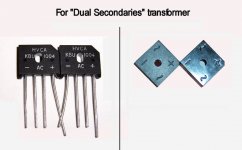
Since that's a dual secondaries transformer, why don't you use dual rectifiers? See photo.
Hey, the big caps can be nice, but you might want to add a pair of 2200uF or 3300uF. Those charge/discharge fast. Refer to CarlosFM 2004 design.
Oh yes, here's a dual rectifier photo.
Hey, the big caps can be nice, but you might want to add a pair of 2200uF or 3300uF. Those charge/discharge fast. Refer to CarlosFM 2004 design.
Oh yes, here's a dual rectifier photo.
Attachments
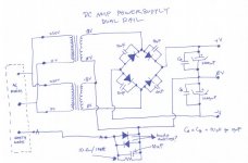
Make sure the phasing of the transformers is correct otherwise it will just be a paralleled half wave rectifier. ie. the ripple frequency will be the mains frequency rather than double the mains frequency.
You have taken one step towards improving the basic PS design. The 10nF across the diodes cuts out most of the switching noise. The next step is adding some film caps across the main reservoir caps, anything from 0.1uF to 10uF is typical. There are many more steps beyond...
You have taken one step towards improving the basic PS design. The 10nF across the diodes cuts out most of the switching noise. The next step is adding some film caps across the main reservoir caps, anything from 0.1uF to 10uF is typical. There are many more steps beyond...
Yes, my target was to get +/- 25volts powering up my split supply amp. But is there any difference between single supply and split supply amp?
I build a chip amp TDA2005 with a single supply, would it make any difference with a split supply design?
ok, now this bridge diode, i believe any 5amp rating bridge should suffice, would it? as for the filter caps, usually 2200uF 50v would be ok.
I build a chip amp TDA2005 with a single supply, would it make any difference with a split supply design?
ok, now this bridge diode, i believe any 5amp rating bridge should suffice, would it? as for the filter caps, usually 2200uF 50v would be ok.
+-25V and 2200uF smoothing does not sound right for an 8ohm speaker.
The peak current into a resistive load is [Vpsu-Vloss]/Rload~=[25-4]/8=2.6amps peak.
Into a reactive speaker load the peak current can be two to three times this value i.e. approaching 7Apk.
The ripple on 2200uF will be enormous.
The peak current into a resistive load is [Vpsu-Vloss]/Rload~=[25-4]/8=2.6amps peak.
Into a reactive speaker load the peak current can be two to three times this value i.e. approaching 7Apk.
The ripple on 2200uF will be enormous.
Indeed. 4700 uF at least in a stereo application. I would have chosen 35 V rating of the caps.AndrewT said:+-25V and 2200uF smoothing does not sound right for an 8ohm speaker.

There are two polarised views on how to smooth the rectified supply,
For high efficiency 8ohm speakers look up Peter Daniel's version with tiny smoothing caps at the amplifier.
For the opposing view look up Carlos FM's snubberised PSU and decoupling at the amplifier.
You ultimately have to make a choice, preferably an informed choice by doing your own experiments and satisfying your system requirements.
you mean Peter's post here:
http://www.diyaudio.com/forums/showthread.php?s=&threadid=123003
or is it somewhere else?
btw, thanks for the advice. currently i have modified my single rail PSU to powerup my TDA2050 amp, with +18.5volt. The PSU have the snub cap on the rectifier, and using a 10,000uF reservoir with 10nF snub cap in paralel. I am using a 3A transformer.
The amp works perfectly, clean sound of my guitar.
casiomax said:as suggested, i've revised the schematics:
Hey, I had suggested the 2200uF as helpers for the 10,000uF. That's sort of like Carlos's 2004 design. Smaller faster caps right at the rectifier, and. . . then. . . the 10,000uF.
")
Also, whatever caps are right at the rectifier, they just get bombed, and you probably don't want to do that to just one pair of caps. So, that's why I suggested the addition of the 2200uF. Let those tackle the rectifier noises. . . thus keeping the 10,000uF clean and cool.
casiomax said:Yes, you did suggest the 2200uF, and thank you, i forget to mention it, sorry, i wanted to edit the reply, but no edit button
thanks again.
That wasn't instead of the 10,000uF. That was in addition to the 10,000uF. Total is 12200uF per rail.
casiomax said:. . . should we paralel 10,000uF with 2200uF ?
Yes.
See the carlosfm snubber power supply from 2004.
It has:
Transformer,
Rectifier,
3300uF, (gets hit with rectifier noise)
10,000uF, (protected and stays clean)
snubber,
output terminals.
And is has these in that order.
Rectifiers make noise. That gets into the nearest capacitor. In the case of the carlosfm 2004 design, his 3300uF gets "hit" with the rectifier noise and some heat, while the 10,000uF stays clean.
That was the example.
the nearest capacitor to the rectifier? does this means components placement plays a role on good PSU?
lets see, a PSU should have filter capacitor in place, on a different board, the chip amp board, on the supply rail there is also a filtering cap, by connection they are actually paralled. but if you say the nearest cap to the recitifer, that means the cap on the PSU.
lets see, a PSU should have filter capacitor in place, on a different board, the chip amp board, on the supply rail there is also a filtering cap, by connection they are actually paralled. but if you say the nearest cap to the recitifer, that means the cap on the PSU.
- Status
- This old topic is closed. If you want to reopen this topic, contact a moderator using the "Report Post" button.
- Home
- Amplifiers
- Chip Amps
- powersupply design question