Hi,
Remember correct layout is far more important than just keep adding caps. The design of the amp should provide ample rejection from noise on the rails anyway.
Massive values of capacitance cause massive charging currents to flow ! Just think about it. The caps get "topped up" every half cycle, and no current flows in the bridge until the peak A.C. voltage across the bridge exceeds the D.C. voltage of the rail. A smaller cap begins to charge earlier in the cycle and the average current is "low". The average ripple voltage will be higher, but it is less "peaky". A large cap causes the bridge to conduct for a very short time, the result being that the peak currents flowing in the bridge, wiring and transformer are massive. The average ripple voltage is lower but more "peaky" Correct electrical layout and particularly grounding counts for much more.
I really want to understand this PSU thing, so the first capacitor connected to the secondary winding is a snub (on other design this was place for each diode on the rectifier), is this correct?
next, i saw a 4.7k bleeder and 3300uF filter cap with 100nF snub, again there is the 10000uF reservoir cap paralel with 1ohm resistor in series with 120nF as a snub.
is it right?
next, i saw a 4.7k bleeder and 3300uF filter cap with 100nF snub, again there is the 10000uF reservoir cap paralel with 1ohm resistor in series with 120nF as a snub.
is it right?
have a look at Carlos' latest mk IV version.
The resistor between the caps emphasises the RCRC action of the filter.
The first C absorbs most of the mains ripple and MUST be rated to take this ripple without overheating.
The second C then does the simpler job of supplying peak current to the following circuits.
The first R is the resistance of the transformer windings and the connecting cables. This is often overlooked as it's relatively small.
The old version post by Daniel is effectively rCrC where the two r are very small, but they still have a filtering effect.
casiomax said:I really want to understand this PSU thing, so the first capacitor connected to the secondary winding is a snub (on other design this was place for each diode on the rectifier), is this correct?
next, i saw a 4.7k bleeder and 3300uF filter cap with 100nF snub, again there is the 10000uF reservoir cap paralel with 1ohm resistor in series with 120nF as a snub.
is it right?
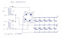
At this point it may be best if you build the rectifier first and get some DC power.
You have a dual secondaries transformer, so you should use two rectifiers.
Try to find KBPC1004 or KBPC1005--model rectifier (do a search).
Those are the plastic squares, and very clearly marked for connection.
See also photo #4 on this page: http://diyaudioprojects.com/Chip/Synergy-LM3875-Gainclone/index.htm
This photo #4 demonstrates how to snub a rectifier. Obviously, BR84 is more durable than it looks.
")
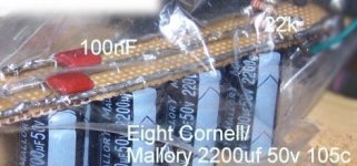
They're Cornell Dublier's "Mallory SEK" which is part # SEK222M050ST and eight of them cost only $10.
That's enough to run most chipamps in stereo config (1 transformer for 2 chipamps).
I built it on a whim, and I had no idea that it would work so well. The deal was that I had tried to run a 100w amp from a 70va transformer. That's not quite right. That transfo is too small.
This power supply was my quick fix. . . and WOW!, the thing does well.
That's enough to run most chipamps in stereo config (1 transformer for 2 chipamps).
I built it on a whim, and I had no idea that it would work so well.
The deal was that I had tried to run a 100w amp from a 70va transformer. That's not quite right. That transfo is too small. This power supply was my quick fix. . . and WOW!, the thing does well.
Attachments
Sure that is one way of getting low impendance... but I think it can be improved ...
On Pri side of transformer I would add 220nf (mains rated for your zone) in series with 1R 17W from AC terminal to AC terminal...
Or you can go even more crazy and add draining resistors inductors etc...
https://www.dxamp.com/images/DXHRII_PSU_sch.pdf
On Pri side of transformer I would add 220nf (mains rated for your zone) in series with 1R 17W from AC terminal to AC terminal...
Or you can go even more crazy and add draining resistors inductors etc...
https://www.dxamp.com/images/DXHRII_PSU_sch.pdf
eketehe said:Hi There,
I find the some caps shows 'Up side' and down side sign.
is there any effect if we set caps 'upside down' like last daniel's pic?
Huh? Can you post a picture or link to web page which shows a cap which has an 'up side' or 'down side' sign. AFAIK, capacitors are not sensitive to orientation.
Maybe there's metal junk all over my desk, and I didn't trust the plastic sack?
That's why the caps are upside down. The Ziplock bag is to keep my clumsy hands off the rails. The thing is upside down because I wanted to see that loose trimmings (on my desk) are not on the rails.
That's why the caps are upside down. The Ziplock bag is to keep my clumsy hands off the rails. The thing is upside down because I wanted to see that loose trimmings (on my desk) are not on the rails.
Oh, you guys are looking for a "secret"?
Sure!
Examples of premium chipamps have included 1000uF, 1500uF, 2200uF, 3300uF and 4700uF capacitors. Looking at the examples, 2200uF is the centrepoint figure.
I have merely "expanded" on an established usage.
Its not much of a secret is it?
What you should "see" in that design is that the first pair of 2200uF caps have absorbed the rectifier noise, leaving the remaining 6600uF clean.
Similar approach:
The older version CarlosFM 2004 design has 3300uF taking a beating from the rectifier, while the 10,000uF stay clean.
There's more to it than that, but clean DC is of primary importance.
eketehe said:I'm sorry dan,
not intend to critic your pic,just asking : stand or hang.
My tought is just like mooly says.
The caps are not mine, i'm affraid have to buy em' to take pics hehe
Oh, no need to apologise. There were some really good questions.
Also, sometimes on new caps (never before used), then I'll either turn them pointed away from me or set a bowl on top of them. Its because I don't want to get hit in the eye with a really stinky flaming cottonball. I've only ever had one ecap to pop, and it wasn't from wiring fault. It was my fault for connecting a new amplifier while the source was plugged in.
Now, I'm sure to let brand new caps warm up (not make demands for 5 min) on their very first use.
Thanks for the reminders!!! I've got to start my own power supply thread soon, and there's much that I do "automatically" for safety, but I need to remember to mention it.
danielwritesbac said:Oh, you guys are looking for a "secret"?
Sure!
Examples of premium chipamps have included 1000uF, 1500uF, 2200uF, 3300uF and 4700uF capacitors. Looking at the examples, 2200uF is the centrepoint figure.
I have merely "expanded" on an established usage.
Its not much of a secret is it?
Not a secret at all. Choose any value from 1000uF up, depending on your budget, space and personal preference for the sloppy Low-uF route or the tight Hi-uF route.
danielwritesbac said:What you should "see" in that design is that the first pair of 2200uF caps have absorbed the rectifier noise, leaving the remaining 6600uF clean.
Similar approach:
The older version CarlosFM 2004 design has 3300uF taking a beating from the rectifier, while the 10,000uF stay clean.
There's more to it than that, but clean DC is of primary importance.
If the caps are in parallel (ie. short lengths of wire between them) they will all have an equal role in smoothing the rectifier. If you want to separate out their roles you will need to separate them with a resistor (say 0.1 to 1 Ohm) or inductor (say 1 to 10 milliHenries) between the +ve connections.
eketehe
. May be you are looking at Leyden Jar . Something like this? http://static.howstuffworks.com/gif/capacitor-5.gif
Are you serious, eka? or just joking again?I find the some caps shows 'Up side' and down side sign.
. May be you are looking at Leyden Jar . Something like this? http://static.howstuffworks.com/gif/capacitor-5.gifglennb said:
Huh? Can you post a picture or link to web page which shows a cap which has an 'up side' or 'down side' sign. AFAIK, capacitors are not sensitive to orientation.
'uh-oh'
the down arrow sign of most elnas n some nichicon ( negative stripe ) doesn't mean that?
I'm sorry...
Thanks,
- Status
- This old topic is closed. If you want to reopen this topic, contact a moderator using the "Report Post" button.
- Home
- Amplifiers
- Chip Amps
- powersupply design question