Where do you get such crazy notions from?
None such thing happens.
I can tell you exactly where such a crazy notion comes from: people tend to use simplistic models when they don't have a deep foundation for a concept.
Someone with an entry level understanding of transformers might not understand that specs are given assuming a certain load. They just know they want 2 x 20 V for their chipamp. And of course "bigger is better" and it still says 2 x 20 V. Pop goes the caps/chipamp.
I ordered the right voltage so it must be the current! Post it on the interwebs, copy/paste, wash and repeat.
See?
If I may say, you and Andrew have enormous foundations in electronics and realllllllly get it. But at the same time this means you have a hard time seeing where and why people get off course. (By the way, I totally get your guys' frustration: you say the same things over and over and sometimes it doesn't seem to sink in)
Misinformation is so common because people don't require unsavory intentions for it to develop and spread.

Last edited:
Basic voltage tests are always useful when building power supplies . In this case
IMHO 20V AC after rectification & filtering is 20X1.41= 28.2V peak (minus diode drop & transformer tolerances typ. +/-10%). Thus one is operating very close to +/- 30V DC limits of LM1875(tremendous heat dissipation). A recipe for disaster waiting to happen
2X15 V AC or 2X18 V AC transformer is recommended.
As for current capacity any thing from 5A or above will be suitable.
Last edited:
There's actually a point to the 36VA~50VA "or else" statements. The point of that is to stop the failures. When using LM1875 chips, there are too-frequent reports of 1 rail's worth of DC offset, aka internal breakage as well as ordinary burnout being commonplace.He's not trying to misinform.
The evidence supporting the need of fuses has become significant enough to call it proof. We must have amplifier board fuses on the schematic. But, I just don't know what amperage and type of fuses to illustrate on the schematic. Help? What do you recommend for the amplifier board fuses?
P.S.
My LM1875 monoblocs with 18+18vac 36va 1a transformers have been rockin out 4 ohm woofers since 2007 (video dated Feb 2008 shows a modest X-max event "tap"): www.diyaudio.com/forums/attachments...one-doing-large-job-lm1875-vids-rockinout.zip Now going on 6 years of reliable service with the transformer serving as limiter, the amplifier output DC offset is still Zero and they'll still X-Max those 4 ohm woofers. That's durable. But durability might be the most unpopular concept on the chip-amp forum. Let's add fuses too!

Yes, those audiosector and chipamp.com kits really are confusing!Hey Daniel
I have managed to get both boards working. Third time lucky
I also managed to get the Audio Sector 3875 kit built. Making the kit helped me to understand what I was doing wrong with the 1875 boards. I bought an extra PS with the 3875 kit. What would be the best way to connect the 2 1875 boards to it. I'm a bit confused with the 3 wires off each amp and the 8 terminals on the rectifier board.
Thanks for all your help
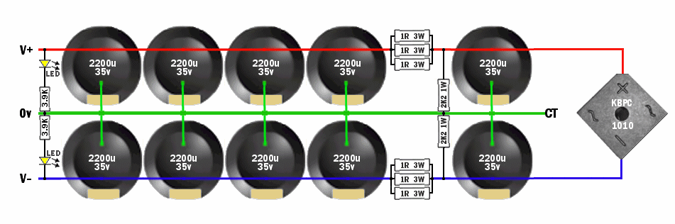
DC side:
You can bond PG+ to PG- Very Sturdy, at the output edge of the power supply board. Now it has a clearly identifiable 0V (CG), and hookup is easy and straightforward, with ordinary 3 conductor DC cable (V+, 0V, V-).
Now it is compatible with star grounding. Also see Decibel Dungeon: Building a Gainclone chip amp power supply.
AC side:
I have a question for you about the AC (transformer) side. Does your 15+15vac transformer or 18+18vac transformer have 3 wires (center tap) or does it have 4 wires (dual secondaries)???
I ask because the audiosector and chipamp.com boards are made for dual secondaries transformers with 4 output cables (thus explaining the 4 vias located directly at the diodes).
However, if you have a center tap transformer with 3 output cables, see post#1 of this thread for something clearly marked for center tap transformer.
Last edited:
You have completely ignored transformer regulation.Basic voltage tests are always useful when building power supplies . In this case
IMHO 20V AC after rectification & filtering is 20X1.41= 28.2V peak (minus diode drop & transformer tolerances typ. +/-10%). Thus one is operating very close to +/- 30V DC limits of LM1875(tremendous heat dissipation). A recipe for disaster waiting to happen
2X15 V AC or 2X18 V AC transformer is recommended.
As for current capacity any thing from 5A or above will be suitable.
Big transformers can have regulation values below 3%, whereas small transformers can have regulation exceeding 30%.
That's an enormous range of output voltage over and above the range caused by the variation of mains voltage which can approach +-10%, but lower in some countries.
Transformer rated voltage probably has a tolerance of around +-1%.
If I got transformers that had a tolerance of +-10%, I would be sending them back demanding a full refund of all costs incurred.
But, the effect is that Dan does misinform.Whoa! ................. He's not trying to misinform.
This is almost certainly down to not understanding what he is doing and not having the ability to translate what he thinks into understandable and plain english.
There are hundreds, or probably many thousands, of foreign language writers/speakers on this Forum who do a better job of writing in plain english. So Dan, being a native english speaker, has little to no excuse for the gobble de gook.
You have completely ignored transformer regulation.
Big transformers can have regulation values below 3%, whereas small transformers can have regulation exceeding 30%.
That's an enormous range of output voltage over and above the range caused by the variation of mains voltage which can approach +-10%, but lower in some countries.
Transformer rated voltage probably has a tolerance of around +-1%.
If I got transformers that had a tolerance of +/-10%, I would be sending them back demanding a full refund of all costs incurred.
Sorry if I got anyone confused, by +/- 10% I meant as a rule of thumb. A full load , no load test of transformer & filter ckt. will reveal the regulation characteristic(more current capacity means tighter regulation characteristics) more accurately. My only point was approaching the max. +/- 30V DC supply limit of LM1875 if using 2X20V AC transformer which may blow the chip due to any reason(transformer or mains supply tolerances).
"The LM1875 delivers 20 watts into a 4 or 8 load on ±25V supplies. Using an 8 load and ±30V supplies, over 30 watts of power may be delivered ... High current capability: 4A" as per TI.
........P.S.
My LM1875 monoblocs with 18+18vac 36va 1a transformers have been rockin out 4 ohm woofers since 2007 (video dated Feb 2008 shows a modest X-max event "tap"): diyAudio Now going on 6 years of reliable service with the transformer serving as limiter, the amplifier output DC offset is still Zero and they'll still X-Max those 4 ohm woofers. That's durable. But durability might be the most unpopular concept on the chip-amp forum. Let's add fuses too!
No problem with using 18V AC tranny but due to 1A capacity limit this will result in poor regulation characteristics. End result - The value of RMS power of your system will be very less than the value of music power output. In other words sine wave testing will yield lower power values.
BTW higher transformer current capacity doesn't means blown chips. Its the approaching of +/-30V DC supply limits of LM1875. Thus instead of "18+18vac 36va 1a transformers" if one uses "18+18vac 36va 10a transformers" which is more than enough or "18+18vac 36va 100a transformers" and law of diminishing returns will start to apply, but still won't damage those LM1875.
If my memory serves me correctly the original gaincard used 170VA tranny with 2200uF filters severely restricting the power output capability of the LM3886 chip.
As for the fuses (another topic for a heated debate) less said is better. Personally I use UPC1237HA with general purpose relays
for spk protection. Damn how I wished I had those Amplimo relaysPS There is no such thing as RMS power. If V (RMS) is multiplied by I (RMS) we get just P & not P (RMS). I've deliberately used RMS power instead of just power
.
Last edited:
Fuses
Here are fuses, same amperage value as shown on the Quasar Kits #50 ("QK50," "K50," "3050KT," LM1875 kits).
And, here is some documentation: http://www.quasarelectronics.co.uk/kit-files/electronic-kit/3050.pdf
Here are fuses, same amperage value as shown on the Quasar Kits #50 ("QK50," "K50," "3050KT," LM1875 kits).
And, here is some documentation: http://www.quasarelectronics.co.uk/kit-files/electronic-kit/3050.pdf
Attachments
Then call it average power.
On a lighter note
Amplifier Power Ratings
A hilarious way to "mathematically derive" PC spk PMPO ratings.
Last edited:
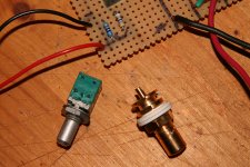
To me it looks like a regular 3 leg pot (front section) and a regular 2 leg switch (back section).
1) does it click if you reach "0" or push/pull the shaft?
and/or:
2) do you measure the pot's resistance across the 3 front legs and 0/infinite across the back ones?
Please post results.
1) does it click if you reach "0" or push/pull the shaft?
and/or:
2) do you measure the pot's resistance across the 3 front legs and 0/infinite across the back ones?
Please post results.
I think it goes like this:Hi Guys-
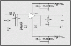
Could someone kindly tell how to wire this pot to the board. I have looked at every diagram I can find and can't find anything with a 5 wire pot and 2 wire board.
Thanks
The back row of 2 contacts are probably a light current on/off switch that you don't need for this project. The front row of 3 contacts are input, output, ground. If you get that sequence mixed up, trying to turn the volume down actually turns it up instead, but except for that possible surprise, it is fairly straightforward. Here's Rod Elliot on the topic: Potentiometers (Beginners' Guide to Pots)
P.S.
One of the links in my signature line below, could have found that information for you, very quickly.
Last edited:
Hopefully it's 9.56 kOhms (i.e. 9560 Ohms), not 9.56 Ohms.
Where the "ground" connects is probably quite important. It will probably connect to the signal input ground, not the enclosure. Think about the path that the current would have to take. It has to flow in a loop, and always will. You never want it to have to "take the long way home".
Where the "ground" connects is probably quite important. It will probably connect to the signal input ground, not the enclosure. Think about the path that the current would have to take. It has to flow in a loop, and always will. You never want it to have to "take the long way home".
Last edited:
- Home
- Amplifiers
- Chip Amps
- Beginner's Gainclone, HiFi LM1875, The Amplifier Board