
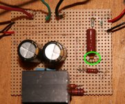
The cap circled in green does shunt RF. That 220pF circled in your photograph is named "RF Blocker."Daniel- is the cap circled in green not the shunt cap?
What you're missing is the cap specifically named "NFB-Shunt Cap."
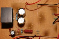
That is the electrolytic cap in the upper left corner of this photo:
Please install it as soon as possible.
You need it. That part will help you get up and running, with less chance of destruction. It blocks amplification of DC. You can use any 440uF or larger cap there.
Well, you did make DC, but you didn't make Split Rail DC.The transformer is wired in parallel. The leads on the transformer are quite short so I have pigtailed them close and run a lead to the rectifier.
For split rail power (standard of audio amplifiers for more than 40 years), you'll want to hook up your transformer correctly.
Here is transformer diagram from Decibel Dungeon:
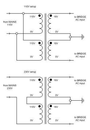
Wire your 9+9 transformer as per the top diagram.
Use 3 conductors of about 8" length, fluxed and soldered to transformer output, which is shown on the right-hand side of the above diagram.
After you complete that task, you have a suitable center tap transformer.
Next,
Connect your new 3 conductor transformer cable to this:
Right-hand side of that shows "~" and "~" for "ac bridge"
and it shows "CT" for center tap, 0v, ground.
That is why you need a 3 conductor transformer cable.
(For reference, V+, 0V, V- is DC output)
Last edited:
Thanks Daniel
Well I've finely got the centre point right. I blew 3 fuses the other day trying to get it following the drawing on DD.
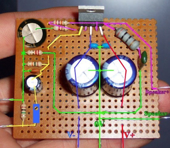
So far one of the amps is working well but the other is just humming fairly loud. No music! I have tried comparing the 2 boards but can't see any difference between them except for one small transistor. Is it possible that I have blown the 1875? I do have an extra that I could put on it. Maybe you can see something I am missing in the photos.
cheers- prezden
Well I've finely got the centre point right. I blew 3 fuses the other day trying to get it following the drawing on DD.
So far one of the amps is working well but the other is just humming fairly loud. No music! I have tried comparing the 2 boards but can't see any difference between them except for one small transistor.
Is it possible that I have blown the 1875? I do have an extra that I could put on it. Maybe you can see something I am missing in the photos.cheers- prezden
Attachments
Hi Prezden,
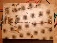
Second photo, error = the NFB-shunt cap is shorted.
Cut the diagonal copper trace (far upper left corner), so that your signal can travel through the NFB-Shunt cap.
NFB-Shunt cap can't work when shorted.
Second photo, error = inter-trace spacing too tight at the chip.
Spread the traces (far left, under chip) to provide more room between speaker output, Pin4 and inverting input, Pin2. There may be a short, either now or soon to be, accidentally between inverting input and speaker output--tiny small-signal input transistor is not strong enough to withstand that. Needs slightly more space there.
Second photo, minor error = too much inductance, the board is too big.
Phenolic perfboard can be sized by scoring it along the holes, both sides, and then flex it. The gauge of cable shown is too thin to be covering excess distance, and that makes excess inductance. I'd suggest to use half as much board.
Quality control check
Before connecting a speaker, connect a DC voltmeter to the speaker output of the amp, set the DC voltmeter to the most sensitive setting and see how many millivolts of DC offset is present. If digital meter, check at other sensitivity settings too, because some digital meters "'possum" when out of range. We want 0.00 volts DC. Don't connect speaker if more than 150mv (a tiny fraction of a volt).
P.S.
Congrats on getting one channel up and running.
P.P.S.
Attached below, is a functional clone of the K50 kit's power board, demonstrating the lowest cost, bare minimum, power supply. This is enough to get up and running. It can be expanded later to a proper supply by upgrading it with CRC resistors (pi filters) to improve resolution and adding larger power supply tank/reservoir to improve bass. But, here's the starter bit without those enhancements.
Attachments
I added an older JISBOS current buffer headphone amplifier I had built some years ago as a preamp to my modified K50 monophonic amp and the result is the audio is fuller, more body...At high preamp input the audio becomes unpleasantly "forward", but otherwise works quite well.
I an using 12V for the preamp and 12,0,-12 for the K50. I think the preamp makes up nicely for the lower amp voltage.
I an using 12V for the preamp and 12,0,-12 for the K50. I think the preamp makes up nicely for the lower amp voltage.
Daniel can you give your input here it would be great if you can shed some light on this predicament
www.diyaudio.com/forums/chip-amps/233131-tda-2030-help.html
www.diyaudio.com/forums/chip-amps/233131-tda-2030-help.html
Those pins flex twice easily, but not a third time.
May I suggest this lightweight precision tool for your next chipamp build?
An externally hosted image should be here but it was not working when we last tested it.
no computer? no access to PDF files? limited research available by smartphone?Daniel can you give your input here it would be great if you can shed some light on this predicament
www.diyaudio.com/forums/chip-amps/233131-tda-2030-help.html
In that case, you'll probably want to explore kits, like these:
Velleman 2 x 30 Watt Stereo Audio Amplifier Kit Education Hobby Kits Education | eBay
LM1875 Power Amplifier DIY Components Kit LM1875T 20W | eBay
Mono Audio Power Amplifier 20W 2X TDA 2003 Assembling Kit Circuit HK1002 | eBay
15W Bride Stereo Amplifier TDA2005 Un Assembled Kit PCB 9 16VDC 2A | eBay
good idea. I might have to stick with kits for the time being- have ordered a kit from Peter Daniels so this one will sit on the shelf for a while. I plugged in the one working amp again and it has failed as well. Some day I will try and get back to these little guys.Thanks to everyone for all your help
The Peter Daniels kit from AudioSector is also going to require adequate split rail power. The failure modes are identical for both LM1875 and LM3875. Likewise, check for DC offset before connecting speaker, and consider using speaker protection of some sort. After you've learned the split rail power circuit, you can fix your LM1875's.
Sounds like overcurrent breakage. What's your transformer's current and voltage and va? And, did you use fuses? Are your speakers 4 ohms or 8 ohms?
LM1875 must not be the weakest link in the chain, but that could happen if run with a too strong transformer or too much load or no fuses.
There's a tiny bit of protection hidden in the power supply example at post1; for example it is a center tap config (less current than dual) and it has the CRC resistors (less current and less noise too). We should also use conservative transformer amperage and fuses.
Last edited:
- Home
- Amplifiers
- Chip Amps
- Beginner's Gainclone, HiFi LM1875, The Amplifier Board