Thanks Daniel- The colour schematic is much easier to understand. The thing that I have trouble with is in translating the schematic to a board layout.
I replaced the ac coupling input cap which did not change the dc offset. So I will try changing the nfb-shunt cap and see what happens. I bought all the components at DigiKey so I wouldn't think the chip is a fake. The dc voltage at the rails is almost exactly the same on both v+ and v- sides.
I replaced the ac coupling input cap which did not change the dc offset. So I will try changing the nfb-shunt cap and see what happens. I bought all the components at DigiKey so I wouldn't think the chip is a fake. The dc voltage at the rails is almost exactly the same on both v+ and v- sides.
This thing really baffles me. I just checked the dc offset again and now it's 21v on both amps.
this happen to me before when i forgot to connect the -25v from the power supply board to the amp board, also check if the signal ground is returned to power gnd, I do it via 2.2ohm resistor
Prezden,
Two questions:
1:
If you measure from +IN pin1, to speaker negative with the ohmeter, how many kohms? (plausible answer is in the range of 10k to 22k)
2:
If you measure from groundside of nfb-shunt cap, to speaker negative with the ohmeter, how many ohms? (plausible answer is in the range of 0R0 to 2R2)
This thing really baffles me. I just checked the dc offset again and now it's 21v on both amps.
Sorry, I don't want to discourage your DIY skills but it would be better if you use LM1875 PCB for this purpose. Also, I see you fighting on two fronts (LM1875 chipamp & RA1 clone)- choose only one project at a time.
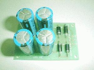
Now for the situation in hand, if the capacitors are really bulged out then-
You might have accidentally reversed the supply
or exceeded the supply voltages
or the capacitors were bad as per Badcaps.net - Badcaps Home
Since one(some times both) of your LM1875 has offset of 21V
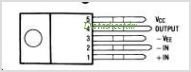
You will have to chk supply voltages at each LM1875 pins(3,5) w.r.t. gnd. itself carefully w/o shorting or slipping probes(see attch.). IMHO you have a loose contact / dry solder issue with power connections causing intermittent offset problems.
Use dummy resistors(10 to 100 Ohms /2W or above ) as test loads or use any elcheapo spk. with series capacitors( as per danielwritesbac) and/or series resistors(10 to 100 Ohms /2W or above ) for sound chk.
Don't connect your B&Ws yet!
Attachments
Last edited:
Prezden,
Have a look at the attachment with "wrong" and "right" input area schematics.
The "wrong" example has TWO things wrong with it.
1). The input Cap is in the wrong place so it prevents input load from working at DC.
2). The input area isn't grounded so that the amp can't find out where 0v/ground is.
Either one of the errors can cause a dc offset problem.
Please check your boards to see if you have one of those errors.
Attachments
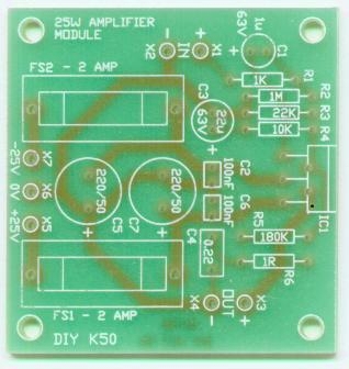
These are recommended:. . .it would be better if you use LM1875 PCB for this purpose.
http://www.electronics123.com/kits-and-modules/CPS50-K50-PCB-only.html
*Replace 180k with 100k; replace 10k with 2.7k; replace 22u with 100u
An externally hosted image should be here but it was not working when we last tested it.
An externally hosted image should be here but it was not working when we last tested it.
This too:
http://www.electronics123.com/s.nl/it.A/id.347/.f
Power supply
An externally hosted image should be here but it was not working when we last tested it.
Hi Daniel- I'm still working on this thing. More stubborn than smart I guess. 
From +pin to speaker neg. I get 8.08 and 8.12
From ground of shut cap I get 0.0 on both sides
cheers
Two questions:
1:
If you measure from +IN pin1, to speaker negative with the ohmeter, how many kohms? (plausible answer is in the range of 10k to 22k)
2:
If you measure from groundside of nfb-shunt cap, to speaker negative with the ohmeter, how many ohms? (plausible answer is in the range of 0R0 to 2R2)
From +pin to speaker neg. I get 8.08 and 8.12
From ground of shut cap I get 0.0 on both sides
cheers
Okay then, more testing. Might not be your fault at all. I suspect that you may have been using a weird tracer type meter (and if digital, that thing is more stubborn than either of us). We should find out now.
Test meter first:
Take a spare electrolytic cap (just the cap--not in a circuit) of a size similar to your nft-shunt-cap. Drain it. Measure it in ohms.
An ACR, ESR or Tracer ohmmeter will report about 0.2 ohms or 0.0 ohms short circuit--Those type meters will not help us block DC because they can't measure DCR. Would be dreadfully confusing!
-or-
A normal or DCR ohmmeter will report either a traveling figure that slowly goes towards open circuit, or simply report open circuit--DC doesn't pass through a normal cap when measured with a normal ohmmeter (those output test dc which is blocked, not test ac).
SO, have you been using a weird ACR meter or a normal DCR meter?
Test circuit wiring:
Does the spare cap that isn't in a circuit measure exactly the same ohms as your nfb-shunt-cap? Disconnect speaker before checking that.
Last edited:
I have looked a long time online and this seems to be the best prices I can find for power transformers;
Power Transformers 18.0V CT Power Transformers | Mouser
VTP 5560 is 100va 5 amps
VTP 18-8800 160va 9amps
Everyone suggests the 160va for "better regulation" but the difference is 1% for a 15 dollar difference in price.
My last question is;
I run some really huge PA amps and none of them have a fuse larger then 5 amps so why do I need a 5 amp transformer for a 40 watt amplifier?
Thanks
Look at the enormous number of replies to the question "what size of transformer do I need" and you will see MANY builders adopting a minimum of around 100VA to 200VA for small amplifiers.
I recommend and have done so dozens of times that the chosen transformer should be from 1times to 2times the total amplifier maximum power. And that your should generally use 160VA as a sensible minimum.
The arithmetic is quite simple.
Two 40W amplifiers give a total of 80W maximum.
The transformer can be from 80VA to 160VA.
I guess it also depends on whether or not you will ever want to run in the upper half of the rated maximum output power range.
These systems are not 100% efficient. Closer to 50%. Maybe you should assume that, in the best case, at least 40% of the energy will be lost as heat.
In that case, a transformer with a VA rating of 1.67 times the amp's rated maximum power would only barely enable you to reach the rated max output.
You should check to see if the amplifier's datasheet has a plot of something like "Power Dissipation vs Output Power". If so (for example, I just noticed that the LM3875 datasheet has it), then look at the dissipation for your max output power, at your power rail voltage. For the LM3875, with 25-volt rails, the dissipation for 40 Watts output is about 32 Watts, which means that you would have to supply at least 72 Watts in order to output 40 Watts. That's a factor of 1.8x. It's worse for higher supply voltages, and does go to OVER 2x, although 2x would be sufficient for most "normal" cases.
Let's see how to select the transformer RMS output voltage rating:
P = i²R
i = √(P/R)
With P_max = 40 W RMS and R = 8 Ohms,
i_max = 2.236 Amps RMS
v_max = R i = 17.9 Volts RMS
But that's at the amplifier OUTPUT, not the transformer.
i_max_pk = 3.16 Amps peak
v_max_pk = 25.3 Volts peak
To get an output signal peak voltage of 25.3 Volts (for 40 Watts into 8 Ohms), your transformer's peak output voltage (1.414 times the RMS output voltage rating) would need to be larger than 25.3 volts, by the rectifier diode drops' specs at 3 Amps (say 2 Volts?) plus the maximum peak-to-peak ripple voltage (say 1.5 Volts, if you use enough reservoir capacitance) plus the amplifier's Vclip voltage (similar to a regulator's dropout voltage) at that rail voltage (say 3 Volts, but it could be 2 to 6 Volts, typically), which gives an estimated peak transformer voltage requirement of 31.8 Volts (peak).
That would require a transformer with an RMS output voltage spec of at least 22.5 Volts RMS (the peak voltage divided by the square root of 2, i.e. about 1.414.).
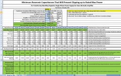
With the worst-case diode, ripple, and vclip voltages estimated above, it would require a minimum reservoir capacitance of 18428 uF per rail, per channel (i.e. double that if two channels are run from he same power rails), in order to just begin clipping at an output power of 40.07 Watts, assuming a worst-case signal (constant DC at the peak level, e.g. square waves, or, very low-frequency bass sine waves).
If you would rather work from a known capacitance value, say 10000 uF per rail per channel, for example, then in that case you could either a) accept clipping starting at 36.54 Watts (worst case) because the max ripple voltage would then be 2.84 Volts (8.85% instead of 5.03%), or, b) get a transformer with an RMS output voltage of at least 23.38 Volts, to increase the headroom to account for the increased ripple (which would then be 2.76 Volts).
There are an infinite number of similar variations that are possible, of course. They are easy to calculate, using Excel's "What If" analysis (to change a cell to a desired value by automatically changing another cell), using the spreadsheet that I last uploaded to:
http://www.diyaudio.com/forums/chip-amps/244320-questions-about-tda2040-based-amp.html#post3698822
(You can ask it to change any of the cells (using the Data-->What If-->Goal Seek menu option) by automatically changing one of the BLUE cells. Only ask it to automatically change the blue cells, which are also the only ones you should change manually.)
But you should first look up your amplifier's Vclip voltage, for the rail voltage you will have. If it's not plotted in the datasheet, you can easily figure it out by looking at the graph of "Power Output vs Supply Voltage": Figure out what max RMS output power you should (theoretically) be able to get, with your rail voltage (assuming zero ripple), with
P_rms = Vpk²/(2R)
or see what rail voltage you'd need for your desired max RMS power, with
Vpk = √(2RP_rms)
and then see what peak (i.e. rail) voltage it ACTUALLY takes to get that RMS output power (by reading it off of the datasheet plot of output power vs supply voltage), and take the difference as Vclip, at that rail voltage.
Also look at your rectifier's datasheet and get the actual voltage drop across the diodes at about 10x the expected rated maximum RMS output current (5x because all of the current has to be supplied only during the short charging period and then use 2x of that, to account for worst-case efficiency of 50% lost as heat).
Then use THOSE Vclip and Vdiode values, in the spreadsheet.
Cheers,
Tom
These systems are not 100% efficient. Closer to 50%. Maybe you should assume that, in the best case, at least 40% of the energy will be lost as heat.
In that case, a transformer with a VA rating of 1.67 times the amp's rated maximum power would only barely enable you to reach the rated max output.
You should check to see if the amplifier's datasheet has a plot of something like "Power Dissipation vs Output Power". If so (for example, I just noticed that the LM3875 datasheet has it), then look at the dissipation for your max output power, at your power rail voltage. For the LM3875, with 25-volt rails, the dissipation for 40 Watts output is about 32 Watts, which means that you would have to supply at least 72 Watts in order to output 40 Watts. That's a factor of 1.8x. It's worse for higher supply voltages, and does go to OVER 2x, although 2x would be sufficient for most "normal" cases.
Let's see how to select the transformer RMS output voltage rating:
P = i²R
i = √(P/R)
With P_max = 40 W RMS and R = 8 Ohms,
i_max = 2.236 Amps RMS
v_max = R i = 17.9 Volts RMS
But that's at the amplifier OUTPUT, not the transformer.
i_max_pk = 3.16 Amps peak
v_max_pk = 25.3 Volts peak
To get an output signal peak voltage of 25.3 Volts (for 40 Watts into 8 Ohms), your transformer's peak output voltage (1.414 times the RMS output voltage rating) would need to be larger than 25.3 volts, by the rectifier diode drops' specs at 3 Amps (say 2 Volts?) plus the maximum peak-to-peak ripple voltage (say 1.5 Volts, if you use enough reservoir capacitance) plus the amplifier's Vclip voltage (similar to a regulator's dropout voltage) at that rail voltage (say 3 Volts, but it could be 2 to 6 Volts, typically), which gives an estimated peak transformer voltage requirement of 31.8 Volts (peak).
That would require a transformer with an RMS output voltage spec of at least 22.5 Volts RMS (the peak voltage divided by the square root of 2, i.e. about 1.414.).
With the worst-case diode, ripple, and vclip voltages estimated above, it would require a minimum reservoir capacitance of 18428 uF per rail, per channel (i.e. double that if two channels are run from he same power rails), in order to just begin clipping at an output power of 40.07 Watts, assuming a worst-case signal (constant DC at the peak level, e.g. square waves, or, very low-frequency bass sine waves).
If you would rather work from a known capacitance value, say 10000 uF per rail per channel, for example, then in that case you could either a) accept clipping starting at 36.54 Watts (worst case) because the max ripple voltage would then be 2.84 Volts (8.85% instead of 5.03%), or, b) get a transformer with an RMS output voltage of at least 23.38 Volts, to increase the headroom to account for the increased ripple (which would then be 2.76 Volts).
There are an infinite number of similar variations that are possible, of course. They are easy to calculate, using Excel's "What If" analysis (to change a cell to a desired value by automatically changing another cell), using the spreadsheet that I last uploaded to:
http://www.diyaudio.com/forums/chip-amps/244320-questions-about-tda2040-based-amp.html#post3698822
(You can ask it to change any of the cells (using the Data-->What If-->Goal Seek menu option) by automatically changing one of the BLUE cells. Only ask it to automatically change the blue cells, which are also the only ones you should change manually.)
But you should first look up your amplifier's Vclip voltage, for the rail voltage you will have. If it's not plotted in the datasheet, you can easily figure it out by looking at the graph of "Power Output vs Supply Voltage": Figure out what max RMS output power you should (theoretically) be able to get, with your rail voltage (assuming zero ripple), with
P_rms = Vpk²/(2R)
or see what rail voltage you'd need for your desired max RMS power, with
Vpk = √(2RP_rms)
and then see what peak (i.e. rail) voltage it ACTUALLY takes to get that RMS output power (by reading it off of the datasheet plot of output power vs supply voltage), and take the difference as Vclip, at that rail voltage.
Also look at your rectifier's datasheet and get the actual voltage drop across the diodes at about 10x the expected rated maximum RMS output current (5x because all of the current has to be supplied only during the short charging period and then use 2x of that, to account for worst-case efficiency of 50% lost as heat).
Then use THOSE Vclip and Vdiode values, in the spreadsheet.
Cheers,
Tom
Last edited:
<snipped>
To get an output signal peak voltage of 25.3 Volts (for 40 Watts into 8 Ohms), your transformer's peak output voltage (1.414 times the RMS output voltage rating) would need to be larger than 25.3 volts, by the rectifier diode drops' specs at 3 Amps (say 2 Volts?) plus the maximum peak-to-peak ripple voltage (say 1.5 Volts, if you use enough reservoir capacitance) plus the amplifier's Vclip voltage (similar to a regulator's dropout voltage) at that rail voltage (say 3 Volts, but it could be 2 to 6 Volts, typically), which gives an estimated peak transformer voltage requirement of 31.8 Volts (peak).
That would require a transformer with an RMS output voltage spec of at least 22.5 Volts RMS (the peak voltage divided by the square root of 2, i.e. about 1.414.).
<snipped>
I should have said "at 22.36 Amps", instead of "at 3 Amps".
As I said near the end of that post:
Also look at your rectifier's datasheet and get the actual voltage drop across the diodes at about 10x the expected rated maximum RMS output current (5x because all of the current has to be supplied only during the short charging period and then use 2x of that, to account for worst-case efficiency of 50% lost as heat).
It will probably typically be 6X to 10X, since the diodes will probably typically conduct for 1/3rd to 1/5th of the time, so 10X is probably better to use, as a worst-case value, if you don't know the phase angles at which the diodes start and stop conducting.
Attached a new version of the spreadsheet. Remove the ".txt" from the filename, before using it with MS Excel.
Attachments
Last edited:
Also, remember to use enough parallel reservoir capacitors, so that the ripple current is small enough when divided between them. For example, if you were going to use 40000 uF for the 40 Watt example above, with the estimated maximum of 22 Amps of charging-pulse current (10X the max RMS output current), then you might want to use four 10000 uF caps in parallel, so that their individual ripple current ratings could be in the 5 to 6 Amp range.
Hi Tom,
Did I calculate this reasonably?
With the little LM1875, we really need to run out of power resources before we run out of SOA, else the lasting may be limited.
At post #1, I've suggested 36va (1 ampere 18,0,18) transformer and a modest power board with 2200u "first caps" followed by 0.33R crc's pi filter resistor followed by 4x2200uF caps per rail at the tank/reservoir section. 36VA*0.67=24W except crc pi filter's resistor will cause less--hopefully the combination of the 36va with the 0.33R holds the amplifier's output to less than SOA. That's not my most efficient power supply effort ever; however, the amplifier *might* not blow up if using a transformer as large as 50va, but larger than that is probably a recipe for disaster.
It is for a little LM1875 monobloc amplifier, so I think 36va is perfect (for hindering amplifier breakage, without overly hindering audio), right?
For Not providing more power than the amplifier can use. . . is the only time I think that two transformers in dual-mono and/or monobloc amplifiers, is an acceptable expense. However, right-size power seems to be a lost art. Meanwhile, fuses. . .
Last edited:
I understand the 18-0-18 1 or 2 amp transformers (I prefer 2 amps) Amps is what creates the heat and when you push chips if you can't keep them cool they let the magic blue smoke out.
I just ordered one of these today for my build. Hope it is the right one.
https://www.antekinc.com/details.php?p=676
I just ordered one of these today for my build. Hope it is the right one.
https://www.antekinc.com/details.php?p=676
Hi Tom,
Did I calculate this reasonably?
With the little LM1875, we really need to run out of power resources before we run out of SOA, else the lasting may be limited.
At post #1, I've suggested 36va (1 ampere 18,0,18) transformer and a modest power board with 2200u "first caps" followed by 0.33R crc's pi filter resistor followed by 4x2200uF caps per rail at the tank/reservoir section. 36VA*0.67=24W except crc pi filter's resistor will cause less--hopefully the combination of the 36va with the 0.33R holds the amplifier's output to less than SOA. That's not my most efficient power supply effort ever; however, the amplifier *might* not blow up if using a transformer as large as 50va, but larger than that is probably a recipe for disaster.
It is for a little LM1875 monobloc amplifier, so I think 36va is perfect (for hindering amplifier breakage, without overly hindering audio), right?
For Not providing more power than the amplifier can use. . . is the only time I think that two transformers in dual-mono and/or monobloc amplifiers, is an acceptable expense. However, right-size power seems to be a lost art. Meanwhile, fuses. . .
Hi Daniel,
Personally, I would always use a "larger-than-necessary" transformer and caps, and limit the output power by limiting the amplitude of the input signal, i.e. turn it down!
That's a little more difficult one to calculate, with the CRC. But it all looks good except for the 1 Amp transformer spec. I would have said at least 1.6 Amps. But that's because I always calculate for a rated max power with worst-case loading, before the onset of clipping, just on principle.
With only 1 amp RMS, the max continuous average output power will be 8 Watts per rail, per channel, indicating a minimum transformer size of roughly 16x2 = 32 VA (16 VA per secondary, since only one rail at a time consumes power but efficiency could be not much over 50%).
The maximum transient average power will be able to be more than that, if the reservoir capacitance is large-enough to make the ripple small-enough to give some headroom.
I was too lazy to simulate it so I looked at the datasheet for the lm1875 and decided that it would sound better at 20 Watts max rather than more. So assuming 8 ohms and using i² x 8 = 20 I got 1.6 Amps max RMS output current.
(I'm working my way toward accounting for the 0.33 ohms.) I estimated the minimum peak rectifier current at 3x the 1.6 A, i.e. 4.8 A. That meant that at the peaks, the 0.33 Ohms would drop at least 1.6 Volts. So, figuring 1.6 for both diodes and another 1.6v for the R, that lowers the transformer output voltage of 18 x 1.414 = 25.46 V to a rail voltage of roughly 22.26 v, at most, when at max output power. If the peak diode current was 5x the 1.6 Amps, then the 0.33 R would drop about 2.6 Volts and the peak rail voltage would be 21.26 V.
So 20 Watts max should be OK: v²/8 = 20 gives v = 12.7 Volts RMS (18 V peak) and we would have roughly 21.3 to 22.3 Volts peak to play with, i.e. 15.06 to 15.77 Volts RMS.
Ah, but the LM1875 will have a minimum of about 3 Volts between the power pin and the output pin (based on datasheet plot of output power versus supply voltage) so the max peak signal voltage plus the ripple voltage have to fit into 18.3 to 19.3 Volts. Now we might be cutting it a little too close.
Since the nominal max peak output signal voltage is 18 V, at 20 Watts average output, you COULD have ripple as large as 0.3 to 1.3 Volts (which is fairly small, actually), with the onset of clipping occurring just at the point when the output was cranked up to 20 Watts. (And that would be true even for the lowest bass frequency, or, for that matter, constant DC at 1.6 Amps.)
I'm looking at it like the capacitance after the 0.33 Ohm is the only reservoir capacitance:
i = C dv/dt so we can use
Cmin = imax x dt / dv
where dv is the max p-p ripple voltage and dt is the time between charging pulses (and we are ASSUMING that one pulse can fully recharge, which is actually usually NOT the case).
So Cmin = 1.6 Amps x 0.008 / (0.3 to 1.3 v) = 0.042667 to 0.009846, i.e. from 42667 uF (yikes!) to 9846 uF, not accounting for ESR.
So, with a larger transformer, i.e. capable of 1.6 Amps RMS @ 18v, using 10000 uF might get the max rated output power to 20 Watts average continuous, before the onset of clipping occurred. Or it might take up to 42667 uF. But who turns it all the way up, anyway? <grin>
In your case, you have 8800 uF and a 1 amp RMS transformer. That gives 1 to 1.65 V across the 0.33 R (for peak diode current of 3x to 5x 1 Amp). So we could assume 2.6 v to 3.3 v comes off of the transformer peak voltage which would give 22.9 to 22.2 Volts for the rail. Then subtract 3v for the LM1875's Vclip voltage (minimum between power and output pins) and that means that the output signal and ripple have to fit into 19.9 to 19.2 Volts.
i = C dv/dt
dv = i dt / C
dv = 1 Amp x 0.008 sec / 0.008800 F
dv = 0.91 Volt (max p-p ripple voltage at the rated max continuous average output power of 8 Watts)
Your max peak signal output voltage should be 1.414 Amp x 8 = 11.3 Volts.
11.3 + 0.91 = 12.21 Volts for signal and ripple, out of 19.2 minimum available, at max output power (8 Watts).
So you should be able to handle higher-power peaks of some size, too.
How much higher?
From above,
dv = 0.91 x i
But for short peaks, looking at i peak,
i = (vrail - dv) / 8
dv = 0.91 x (19.2 - dv) / 8
dv = 0.91 x 19.2/8 - 0.91 x dv/8
1.1236 dv = 2.184
dv =1.94 V
So
19.2 - 1.94 = 17.26 V signal peaks possible without clipping.
That allows for 37.2 peak Watts, i.e. short periods of 18.6 Watts average.
How short is short? Just for fun,
i = C dv/dt
dt = C dv / i
dt = 0.00880 x 1.94 / (17.26/8)
dt = 0.0079 sec,
which is slightly shorter than one charging period (assuming 60 Hz mains and full wave rectification, which gives a charging period of 1 / (2 x fmains) = 1 /120 = 0.00833 sec). I have no idea what physical significance that dt might have, except that if you did it continuously, the caps would slowly drain and the rail voltage would fall continuously.
Last edited:
- Home
- Amplifiers
- Chip Amps
- Beginner's Gainclone, HiFi LM1875, The Amplifier Board