 I think you are trying to paste the image in, that won't work.
There could be three problems that I can see:
a.)
The local decoupling is shown well away from the chip pins. Where have you located them?
b.)
The RF attenuation capacitor is missing. Have you added one?
c.)
Reducing the gain increases the feedback. This may require adjusting the stability components.
a.)
The local decoupling is shown well away from the chip pins. Where have you located them?
b.)
The RF attenuation capacitor is missing. Have you added one?
c.)
Reducing the gain increases the feedback. This may require adjusting the stability components.
Yes the decoupling caps are away from the pins! They are in the center... first caps below the TDA2030.
By RF attenuation do you mean one at the input? I am not sure I understood that!
I used 1K since I had those lying with me in MFR. (All resistors used are MFR) I was not aware reducing gain would cause much issue! What do you suggest?
By RF attenuation do you mean one at the input? I am not sure I understood that!
I used 1K since I had those lying with me in MFR. (All resistors used are MFR) I was not aware reducing gain would cause much issue
! What do you suggest?Another version of LM1875
Thanks to Daniel and Andrew for their advises.
I have finished this version after reading over and over posts on this thread as well as some PMs with the TS and getting motivated to try myself a point to point version.
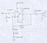
Perhaps anyone would like to comment on the schematic and how I could improve the amp. Some of you probably don't like the idea of having a series output capacitor.
But this one, to me, sounds better than my previous LM1875 (this PCB Amplifier PCB for TDA2030/LM1875 - oddWires but without the power supply) plus a series output capacitor of 4700 uF for each channel.
Choice of the components is mostly due to the available components at hands.
Thanks to Daniel and Andrew for their advises.
I have finished this version after reading over and over posts on this thread as well as some PMs with the TS and getting motivated to try myself a point to point version.
Perhaps anyone would like to comment on the schematic and how I could improve the amp. Some of you probably don't like the idea of having a series output capacitor.
But this one, to me, sounds better than my previous LM1875 (this PCB Amplifier PCB for TDA2030/LM1875 - oddWires but without the power supply) plus a series output capacitor of 4700 uF for each channel.
Choice of the components is mostly due to the available components at hands.
Attachments
More information needed: What else is the speaker ground connected to?
P.S.
Reference point missing, and so is most of the power: I have not used the LM1875 at 12+12VDC power. For me, the 6 watts wouldn't have quite enough headroom to assure quality output. For reference, 15+15VDC can get you almost 10 watts.
P.S.
Reference point missing, and so is most of the power: I have not used the LM1875 at 12+12VDC power. For me, the 6 watts wouldn't have quite enough headroom to assure quality output. For reference, 15+15VDC can get you almost 10 watts.
Thanks to the response and merry Christmas to you all. Sorry for interrupting your Christmas celebration by this post.
Speaker ground is connected to the circuit common ground (zero) together with input ground, NFB Shunt Cap negative. Pins 3 and 5 of the chip is connected to +/- 12 v.dc.More information needed: What else is the speaker ground connected to?
Hi Andew, I'm sorry, I'm not following. What do you mean the chip need to send input offset current?post387
does the chip need to send input offset current somewhere?
From the datasheet page 2, do you mean that R2 (22k) must exist after C1 before entering +IN? Thanks. I'll correct in my implementation and will use the datasheet value (22k).
Can you also elaborate on zobel network? I read from Rod Elliot's page (ESP), he put the zobel (10ohm + 100nF) before output cap (4700uF). I also intend to add the zobel and probably follow his practice.
Can you also elaborate on zobel network? I read from Rod Elliot's page (ESP), he put the zobel (10ohm + 100nF) before output cap (4700uF). I also intend to add the zobel and probably follow his practice.
Does the datasheet state an input offset current?
Does the datasheet show a route for this to escape?
You have a blocking cap on the +IN !
End Year Gift
Hi,
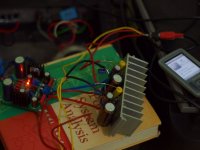
This is the updated version of my previous post. +/-12 volt dc supply gives the amp enough power to operate without putting too much heat to the 1875.
Load is a two-way speaker taken from Philips MCL707 and it sounds great.
This version works better than my previous LM1875 version (Amplifier PCB for TDA2030/LM1875 - oddWires) of which danielwritesbac said it has too much mids.
I built it point to point and happy with the result.
Thanks to danielwritesbac and AndrewT for their helps in building this amp.
Happy New Year!
Hi,
This is the updated version of my previous post. +/-12 volt dc supply gives the amp enough power to operate without putting too much heat to the 1875.
Load is a two-way speaker taken from Philips MCL707 and it sounds great.
This version works better than my previous LM1875 version (Amplifier PCB for TDA2030/LM1875 - oddWires) of which danielwritesbac said it has too much mids.
I built it point to point and happy with the result.
Thanks to danielwritesbac and AndrewT for their helps in building this amp.
Happy New Year!
Attachments
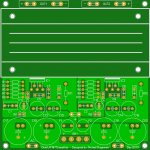
I would like to build 2 PCBs as well with the LM1875.
I have made a design for perf board, as the pitch is 2.54mm and only 5x5cm big
Is my layout correct ?
I made a dual LM1875 PCB with onboard heatsink and powersupply.
I think this would be very nice as first time project
Heatsink: http://www.fischerelektronik.de/web_fischer/en_GB/heatsinks/A04/Extruded%20heatsinks%20for%20PCB%20mounting/PR/SK68_/$productCard/parameters/index.xhtml
100mm version
Attachments
Last edited:
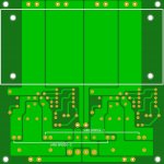
On that very large board, please be sure that the output AND intake areas of the heatsink are Not blocked off.
Heatsinks need air in and air out.
SO, does your board mount vertically rather than the typical horizontal?
The location of F1 and F2 is useless for protection because they'll have to be strong enough to instantly charge up your main tank/reservoir capacitance, which means the fuses are far too strong to protect tiny LM1875 chips. The location for protecting the chips would be closer to the chip and in-between the small and large power caps. You'll need 2 fuses per each chip. . . because if the fuses are strong enough to protect two chips, then they will fail to protect one chip. See also the QK50 kit, Quasar K50 lm1875 because it shows the location of the fuses.
Hi @availlyrics,
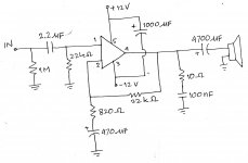
I'm not quite following you @ about speaker capacitor being coupled. If you talk about the 1000 uF, then it is actually a substitute for two of 470 uF for each rail as in Danielwritesbac's design. Since the voltage rating of my 1000 uF (a good cap I have when I built this) is 35 v, then it is just fine to install it across 24 v (+/- 12 v).
If you mean the series output capacitor, you can check our previous discussions in post #372 ~ #376, I originally had other version of LM1875, an XY HiFi Board and it suffers from too much mids. I then tried to put a series capacitor of 4700uF and it sounds better to my ears. Since then, I think it is good to still employ this output capacitor for my implementation of LM1875.
For the NFB-shunt capacitor, Danielwritesbac suggest higher value, my older LM1875 amp employs only 22 uF and that was probably one of the source of suffering from too much mids.
As for the zobel, 10R + 100 nF, I just copied from other design, especially from Rod Elliot's DoZ. He put this zobel (same values) before the output cap. In my implementation, I solder them directly to speaker terminals.
Hope it helps. Thanks.
Enjoying the last days of 2013 by building this amp P2P.
I'm not quite following you @ about speaker capacitor being coupled. If you talk about the 1000 uF, then it is actually a substitute for two of 470 uF for each rail as in Danielwritesbac's design. Since the voltage rating of my 1000 uF (a good cap I have when I built this) is 35 v, then it is just fine to install it across 24 v (+/- 12 v).
If you mean the series output capacitor, you can check our previous discussions in post #372 ~ #376, I originally had other version of LM1875, an XY HiFi Board and it suffers from too much mids. I then tried to put a series capacitor of 4700uF and it sounds better to my ears.
Since then, I think it is good to still employ this output capacitor for my implementation of LM1875.For the NFB-shunt capacitor, Danielwritesbac suggest higher value, my older LM1875 amp employs only 22 uF and that was probably one of the source of suffering from too much mids.
As for the zobel, 10R + 100 nF, I just copied from other design, especially from Rod Elliot's DoZ. He put this zobel (same values) before the output cap. In my implementation, I solder them directly to speaker terminals.
Hope it helps. Thanks.
@plgsekip
Why are the spk. capacitor coupled & not directly since the power supply is dual rail?
Enjoying the last days of 2013 by building this amp P2P.
You have 1000u across the rails? Okay, that will do for the positive rail's decoupling. But, there's a cap missing. The negative rail needs a cap added from the V- pin to 0v and that cap size is in the range of 10u to 470u. http://www.diyaudio.com/forums/power-supplies/240955-resevoir-capacitors-chip-amps.html#post3631062 <--link to asymmetrical decoupling discussion.
...If you mean the series output capacitor, you can check our previous discussions in post #372 ~ #376, I originally had other version of LM1875, an XY HiFi Board and it suffers from too much mids. I then tried to put a series capacitor of 4700uF and it sounds better to my ears.
....
Sorry for the confusion, I meant series o/p 4700uF capacitor not needed for this job. Any ways since you are enjoying the sound(frequency response, damping,e.t.c. will be worse than a directly coupled o/p though), no problem. In-fact now your spk. are protected from DC (due to component or power supply failure), the most serious and perhaps the only problem with a direct coupled design.Even I used to like the sound of series o/p 4700uF capacitor in my earlier Norge 2030 single supply amp as compared to my NAD C352 direct coupled amp. But after continuous listening tests I've started to like the sound of direct coupled amps.
@danielwritesbac I agree with you,pair of 1000uf & 0.1uF from +/- rail to Gnd is highly recommended.
Happy New Year To All
Last edited:
@availlyrics and @danielwritesbac
Thanks for the notification. May I ask for further explanation. Do you think there will be some kind of problems or perhaps damage to the amp if I do not put another cap across -12v and ground?
Or will there be an improvement in "sonic performance" if I put the cap?
@availlyrics: You are right about the series cap. but I think I'll leave it there for a while until I make another one without it and compare the result. :-D
- Home
- Amplifiers
- Chip Amps
- Beginner's Gainclone, HiFi LM1875, The Amplifier Board