This is for the purpose of an accessable hifi gainclone amplifier, it is in reference to http://www.diyaudio.com/forums/showthread.php?s=&threadid=122062, and it is by request.
Without further ado, here's LM3875 by hand, at low cost, and easily made by following the "play by play" photographic format.
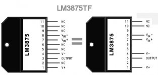
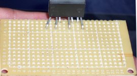
Since we're not shipping PCBs through the mail on this project, here's a photo of LM3875 that shows the hookups we're going to use. The purpose is wide spacing for easy soldering on phenolic board, which is available anywhere.
Without further ado, here's LM3875 by hand, at low cost, and easily made by following the "play by play" photographic format.
Since we're not shipping PCBs through the mail on this project, here's a photo of LM3875 that shows the hookups we're going to use. The purpose is wide spacing for easy soldering on phenolic board, which is available anywhere.
Attachments
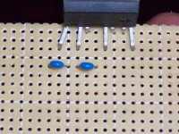
Following along with the directions in http://www.national.com/ds.cgi/LM/LM3875.pdf, we're supposed to put 100nF capacitors, at the rails, and close to the chip.
100nF is also known as 0.1uF.
100nF is also known as code 104, and there's probably a "104" printed on your capacitor.
You can use ceramic or polyester, or polypropylene at any price point or brand as long as it has a "104" printed on it.")
See photo for their location:
100nF is also known as 0.1uF.
100nF is also known as code 104, and there's probably a "104" printed on your capacitor.
You can use ceramic or polyester, or polypropylene at any price point or brand as long as it has a "104" printed on it.
See photo for their location:
Attachments
Let me introduce you to your new best friend for instant success with soldering:
Electronics grade flux. For example:
http://www.radioshack.com/product/i...p=&sr=1&origkw=flux&kw=flux&parentPage=search
You get a small, inexpensive toy paint brush and apply a thin coat wherever you expect the solder to stick.
Electronics grade flux. For example:
http://www.radioshack.com/product/i...p=&sr=1&origkw=flux&kw=flux&parentPage=search
You get a small, inexpensive toy paint brush and apply a thin coat wherever you expect the solder to stick.
Attachments
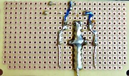
Hookup of the power circuit:
We get 3 pieces of hookup wire.
That's generally a 24ga solid copper.
These 3 pieces are as long as the whole project.
The one ground wire, down the middle, is twice as thick.
It "stops" at the centerpoint between the little 100nF caps.
The two "hot" lines (V+ and V-) are given a tiny little "hook" on the end, so that there's certainly a secure connection to the V+ and V- pins of the chip. Reference post#1 for their location, just to be sure.
See picture.
It isn't necessary to make the sort of mess that I did here. Just the general hookup will work fine.
In case your board doesn't have the pads, just bend the capacitor pin over top of the hookup wire for a firm connection prior to soldering. That technique is shown at the centerpoint of the two 470uF caps here.
Attachments
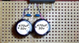
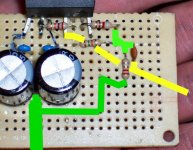
danielwritesbac said:Lets add a pair of either 470uF or 330uF.
These are the onboard capacitors for power.
See picture.
Marked in pen is where the wire will go.
thank you, thank you.
this is the kind of pictorial assay that is tremendously helpful for us total dummy newbies.
gychang
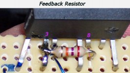
Its time to install the feedback resistor.
What it does:
This is one of a pair of resistors that make up the NFB.
The NFB, Negative Feedback Loop sets the gain of our amplifier.
Do it clean:
Lets take a moment to rub the end of the soldering iron with some steel wool, or you can use a damp sponge.
The part:
Lets get a 27k resistor. Its color code is red, purple, orange.
EDIT: Shown is ordinary 1/4watt carbon from the variety bag at the local Radio Shack. Of course you can use the blue (metal) if you like. The important part is that both NFB resistors (27k and 680R) be made of the same materials.
Prepare:
Have a look at the photo.
Paint metal with flux so the solder will stick.
Directions:
Make a little hook with one of the resistor leads (see photo) and trim it short.
First, hook this over pin3 and solder into place.
Second, just stuff the other end down the hole that's right in front of pin8, and solder it to pin 8.
See photo.
*Allow a bit of space so that the resistor doesn't touch other pins.
Attachments
gychang said:thank you, thank you.
this is the kind of pictorial assay that is tremendously helpful for us total . . . newbies.
gychang
Oh, you're welcome indeed!
The design on this thread has some answers to the many questions that I've been asked in public and in private.
That includes goals of general compatibility with speakers and sources, as well as a non-botique approach that will allow it to work just as well with recycled, free, or hobby-shop parts parts as it does with name brand parts. Use what you have and what you can find.
Bluto said:Hi Dan -
This is real good.
Peter had said in his thread he wanted questions/comments directed via PM.
How do you want yours? I'm still gona have several.
Thanks - Bluto
Thank you!
Right now, I'm doing assembly. So, post any assembly-related questions concerning this particular amplifier design.
Alternative designs and/or exploring more options for this design are on this thread: http://www.diyaudio.com/forums/showthread.php?postid=1509667 and that's where the "other" sort of questions go.
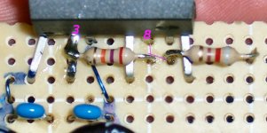
Completing the NFB:
We get an 820 ohm resistor. Its color code is gray, red, brown.
It goes from pin8 to ground. Just hook it to pin 8 for now--we'll ground the other end soon.
See photo.
Edit: Leave a bit of space so that it doesn't touch any pins.
We get an 820 ohm resistor. Its color code is gray, red, brown.
It goes from pin8 to ground. Just hook it to pin 8 for now--we'll ground the other end soon.
See photo.
Edit: Leave a bit of space so that it doesn't touch any pins.
Attachments
Tools:
Did your solder run together?
If so, use a desoldering iron. Its the safest way to make corrections.
For example:
http://www.radioshack.com/product/i...ng+iron&kw=desoldering+iron&parentPage=search
Tools:
Did your fingers get really hot or was it hard to work in a tight space?
Hemostats/Forceps can help. For example:
Did your solder run together?
If so, use a desoldering iron. Its the safest way to make corrections.
For example:
http://www.radioshack.com/product/i...ng+iron&kw=desoldering+iron&parentPage=search
An externally hosted image should be here but it was not working when we last tested it.
Tools:
Did your fingers get really hot or was it hard to work in a tight space?
Hemostats/Forceps can help. For example:
An externally hosted image should be here but it was not working when we last tested it.
Bluto said:Peter had said in his thread he wanted questions/comments directed via PM.
That was to peranders only, everybody else can ask me directly in a thread.
Peter Daniel said:That was to peranders only, everybody else can ask me directly in a thread.
Hey, I don't mind questions either, its just that'd I like to finish this assembly first.
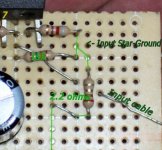
Next up, the input star ground.
This is the ground points for both the NFB and the input.
We need a 15k resistor for input impedance (a 15k load).
Its color code is brown, green, orange.
This connects between pin 7 (input) and ground.
To prevent hum, we'll use a 2.2 ohm resistor to connect between power ground and input star ground.
To make it easier to see where the input cable goes, I ran it right underneath the input impedance resistor.
See photo:
Attachments
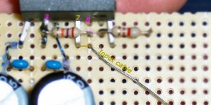
Here's a better picture of the input star ground, with color codes.
Green is a ground.
Yellow is the input cable.
Oh, but a new little addition has arrived. To prevent noise, there's an RF filter. That's a simple little ceramic capacitor of 330pF value. It will have "331" printed on it. You can use any nearby value (471, 221, etc. . .).
This is placed as a load (between input cable and ground), where it blocks frequencies that are higher than the audio band.
See picture:
Attachments
- Status
- This old topic is closed. If you want to reopen this topic, contact a moderator using the "Report Post" button.
- Home
- Amplifiers
- Chip Amps
- Beginner's Gainclone, LM3875, The Amplifier Board