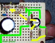
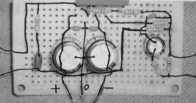
Since this amplifier is designed to run without a preamp, we need a few passive parts.
A 2.2uF electrolytic cap or a smaller value poly cap.
A 470 ohm resistor.
A 1 million ohm resistor (1M).
The capacitor blocks DC to protect the amplifier and speakers, while the two resistors help combat noise.
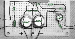
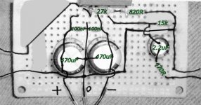
This photo shows the three parts added.
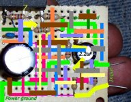
It shows the path of the input cable in yellow, while the ground is shown in green.
A 2.2uF electrolytic cap or a smaller value poly cap.
A 470 ohm resistor.
A 1 million ohm resistor (1M).
The capacitor blocks DC to protect the amplifier and speakers, while the two resistors help combat noise.
This photo shows the three parts added.
It shows the path of the input cable in yellow, while the ground is shown in green.
Attachments

MJL21193 said:What it's going to look like soon...nice and simple.
Yeah, that right side looks awful.
Edit: Its a nice passive pre there, and I did so much better job on the little LM1875 board.
The problem is that (this time) I used eboard (with pads) and that wasn't a convenience at all! I've spent much extra time trying to keep the circuits away from all those extra pads. Darn.
Maybe I should give it a redo on plain veroboard, before going any further?
Attachments
Time for questions
Okay guys, its time for questions and comments, if you like.
This amplifier needs a power supply board, that we'll cover soon, or you can use this: http://www.electronics123.com/s.nl/it.A/id.347/.f
If you're looking for an easier project, or more information, refer back to the index: http://www.diyaudio.com/forums/showthread.php?s=&postid=1509667#post1509667 because there'll be a nifty little LM1875 (soon), with plenty of power and good sound for Gychang's B20 speakers.")
Okay guys, its time for questions and comments, if you like.
This amplifier needs a power supply board, that we'll cover soon, or you can use this: http://www.electronics123.com/s.nl/it.A/id.347/.f
If you're looking for an easier project, or more information, refer back to the index: http://www.diyaudio.com/forums/showthread.php?s=&postid=1509667#post1509667 because there'll be a nifty little LM1875 (soon), with plenty of power and good sound for Gychang's B20 speakers.
is that all you're giving us?
What about a list of components for the simplest version.
Then a list for the simple version
Finally a list for the normal version.
Then explain how to recognise each of the components.
and explain how to interpret all the code numbers and letters and colours for each.
and selecting suitable voltage ratings for critical components.
Check everything is available before starting.
Then check measure in case you're colour blind.
Then how to solder.
Then about bending component legs away from the body of the component
And then about supporting the component leg while bending to avoid stress in the component body to leg connection.
and what tools must be available and what are optional and what to use if the optional are unavailable.
And the list of newbie required answers goes on and on.
This was supposed to be a pictorial story board for newbies that could not follow written instructions.
But that was what started this thread, a request for an idiots' guide to BUILDING a chipamp, without all the complication of WHY it works. And that it should be done in pictures.ratza said:No offence AndrewT, but if they don't know what are the numbers, colours, sizes, voltages and so on, this is way to dangerous for a newbie. The power supply is quite powerfull and newbies should start with way simpler projects, not necessary audio.
Ratza -
You're just wrong Man. Even Peter Daniels guide has soldering instructions. I rewired a 3 Story Victorian home from top to bottom starting with gutting entire place. Gainclones still give me questions.
Hi Andrew -
Somewhat harsh but, Yes, these are issues newbees want to deal with.
So arguing doesn't start here as well how bout those of us who claimed initial interest relegate ourselves to being called 'Morons' to make all brighter bulbs shine further into the night in their own Castles?
Dan -
Haven't had time yet, appreciate all you've done but many, many questions to come. Hopefully this weekend.
Bluto
AndrewT said:
What about a list of components for the simplest version.
Then a list for the simple version
Finally a list for the normal version.
That's a really good idea!
Its not really several versions, though. Its the same amplifier given with or without the optional hum-reduction components.
Simplest version (the "core" amplifier). . .
One channel is listed--so, for stereo, get twice as much.
IC chip:
- LM3875TF or LM3875T+heatsink insulator
*Either needs a sufficiently large heatsink
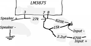
NFB, Negative Feedback Loop (two resistors that set the gain):
- A 27k resistor
- An 820 ohms (820R) resistor
Input circuit:
- A 15k resistor (goes directly from pin 7 to ground)
- A 2.2uF capacitor (made-for-audio electrolytic or any "poly" cap)
- A 470 ohm resistor (can choose any value between 0 and 1k, depending on results--470 ohm is the centerpoint value)
*Using a potentiometer is suggested
Power:
- 1 pair of 100nF capacitors (50v or larger capacity)
- 1 pair of 470uF (or 330uF) electrolytic capacitors (50v or larger capacity) the stripe of both caps faces the "v-" side.
*This amplifier also requires an additional power supply board
Optional components:
- A 1 megaohm load (1m resistor) at the amplifier input terminals (from + to - of the input signal cable--at the amplifier board)--performing hum reduction utility.
- A 330pF cap from pin 7 to ground (in addition to the 15k input impedance resistor)--performing an RF blocking utility.
- A 2.2 ohm resistor (a value from 2.2 to 4 ohms is fine), from power ground to input star ground (connects to the 15k, 330pF, and 820R listed above)--performing a "groundlift" utility.
- A speaker output zobel consisting of a 100nF cap (or 47nF cap) and a 10 ohm resistor (resistor goes from pin3 to the cap--and the other end of the cap goes to speaker ground).
*The speaker output zobel may, optionally, be located at the speaker output terminals of the amplifier chassis.
Component selection:
- Resistors? 1/4 watt resistors will give good results. You may use a more-durable 1/2 watt resistor at the speaker zobel.
- Potentiometer? The A20k Dual Gang (20k stereo pot) is a generally compatible value, although there are many other working options.
- Power supply board? A rectifier (makes the AC from your transformer into DC for your amplifier) and at least 2 pair of 2200uF caps per rail.
*Power supply board needs further discussion; however, that topic is beyond the scope of this thread. A kit example was given earlier. We will construct power supplies later. Those are easier, but there needs to be a safety discussion located on the power supply thread.
Errata:
There is a possibility of loud, rumbling, "one note thud" bass when an input filter capacitor (the 2.2uF above) is "too much" for your system. If this happens, use a much smaller value poly type capacitor. How much smaller? A general figure is 0.5uF for poly input cap. You may, or may not, experience the loud bass errata.
Anything else?
Wow! Thank you.
As promised, here's LM1875, prettier and easier: http://www.diyaudio.com/forums/showthread.php?s=&postid=1513113
Its shown with the same circuit, but LM1875's are easier to build, fairly instant hifi, and the price of a hamburger, so it might be a good reference.
As promised, here's LM1875, prettier and easier: http://www.diyaudio.com/forums/showthread.php?s=&postid=1513113
Its shown with the same circuit, but LM1875's are easier to build, fairly instant hifi, and the price of a hamburger, so it might be a good reference.
Fine Tuning Time!
Well, folks, it seems that I need to cover "what to do" if you get DC offset in excess of 85mv or so.
Chipamps can vary by gain setting, and can vary per each individual sample (of chip).
There are also some inbuilt voicing options--using standard values, not botique components. Although this project played very detailed (the clearest I've ever heard), it was just too forwards for my own personal tastes.
I wasn't the only one to notice.
Specifically, it failed to cast soundstage both forwards and rearwards. That's fairly typical for a basic chipamp, except that LM1875 (easy) and TDA7294 (unreasonable pinout) can be arranged "laid back" without caveats.
One way to level a LM3875 or LM3886 is the CarlosFM snubber power supply (by "values" approach), and that sinks the mids.
Another way is to install 1500uF or 2200uF caps at the amplifier board. Specific models make best results (botique approach), and that adds a bit of cap noise (perceived as a blur), which raises the midbass. You see why that's a botique approach, because the "right" cap (obviously the same one used at AudioSector), adds midbass without a noise (without a blur).
Yet another way is demonstrated on page 16 of LM3875.pdf. That "hi-ref" style is a big fight on component selection (botique), and if you win that fight, its nonstop goosebumps. Note the "if."
However, there are simple options already on this board, and, by request, I'll go about exploring them.
Voicing options:
1). A selection of 220uF, 330uF or 470uF power caps
2). Groundlift resistor between 0 (just a wire) and 10R
3). Input compensation resistor between 0 and 1k
4). Optional gain settings / input impedance mod
My apologies that the project wasn't as "generally compatible" as intended. The LM1875 on the exact same circuit does deliver. So, I'm a little bit puzzled at the difference. But, I'll find out!
Right now, it seems that I didn't quite hit the centrepoint figures, so some people had fantastic results, while others had the urge to email. . .
The good news is that LM3875 and LM3886 seem to be similar in their needs. So, after this effort (fine tune), I'll have a nice "head start" towards the LM3886 board.
- Status
- This old topic is closed. If you want to reopen this topic, contact a moderator using the "Report Post" button.
- Home
- Amplifiers
- Chip Amps
- Beginner's Gainclone, LM3875, The Amplifier Board