quote:
Two Bridges. If you use more than two life becomes interesting.
I am fairly interested in interesting things, but don't see something interesting here . Could anybody provide some clarification here. It was my guess that if only one trafo is used for 2 channels, a set of two bridges per channel (4 total) would be helpfull, each channel has it's 'own' filter caps whereas the shared bridge configuration has by definition also shared filter caps. Is this correct?
edm
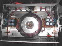
The gainclone that i am listening to for more than 200 hours in total, is supplied by 1 x-former (300W), , 4 bridges (2/channel) and the associated caps. I didn't have any "interesting" incidence so far.
I too wonder what Kuei Yang Wang does mean by that.
Mr. Kuei can you give some further explanation please?
Regards
George
As mentioned before, I blew my fuses when I used one toriod and six bridges for three channels. Now I use two bridges for three channels, and it works. Have no idea why....
But maybe I wired incorrectly. I wired the three pairs of bridges in parallel to the secondaries. Same wiring as now with only one pair of bridges.
Maybe something to do with having three inverted channels?
But maybe I wired incorrectly. I wired the three pairs of bridges in parallel to the secondaries. Same wiring as now with only one pair of bridges.
Maybe something to do with having three inverted channels?
Nah.2Bak said:As mentioned before, I blew my fuses when I used one toriod and six bridges for three channels. Now I use two bridges for three channels, and it works. Have no idea why....
But maybe I wired incorrectly. I wired the three pairs of bridges in parallel to the secondaries. Same wiring as now with only one pair of bridges.
Maybe something to do with having three inverted channels?
Very likely it has to do with current limiting by the bridge. Because the caps have to be loaded on the startup of the amp, a large current peak will go through the bridges and fuses. I could imagine that three pairs of bridges have a larger current capability, thus bringing a larger current through the fuse, increasing the chance of a burned fuse.
Besides, I suspect that your fuse is rated to small. 1000 uF caps are not that large for a supply. What fuse do you use ?
Fedde
RE: Rectifiers and PSU
Hi,
No offense but... why do I get the feeling that most of you don't understand the benefits of what Fred is desperately explaining?
Read and reread...these are little gems he's throwing your way guys.
Cheers,😉
Hi,
No offense but... why do I get the feeling that most of you don't understand the benefits of what Fred is desperately explaining?
Read and reread...these are little gems he's throwing your way guys.
Cheers,😉
Frank,
is your remark also directed to me? Because I had a feeling that Freds clear explanation made perfect sense to me. After your comment I've reread his post two times more, but my understanding of Freds post remains the same. I don't see any conflict between my question and Freds post. If there is please enlighten me since I am not unwilling to learn.
is your remark also directed to me? Because I had a feeling that Freds clear explanation made perfect sense to me. After your comment I've reread his post two times more, but my understanding of Freds post remains the same. I don't see any conflict between my question and Freds post. If there is please enlighten me since I am not unwilling to learn.
BURNING BRIDGES.
Hi,
No Sir...you only asked questions in your latest post as I recall it...sleep tight tonight.😎
Way to go, I wish I saw this attitude more often.😉
I just want to say, on closing, that I hope Fred's wisdom is read by the tube guys as well, it is really ahead of time.
Waitin' for Jocko... 😉
Hi,
is your remark also directed to me?
No Sir...you only asked questions in your latest post as I recall it...sleep tight tonight.😎
If there is please enlighten me since I am not unwilling to learn.
Way to go, I wish I saw this attitude more often.😉
I just want to say, on closing, that I hope Fred's wisdom is read by the tube guys as well, it is really ahead of time.
Waitin' for Jocko... 😉
fedde said:
Nah.
Very likely it has to do with current limiting by the bridge. Because the caps have to be loaded on the startup of the amp, a large current peak will go through the bridges and fuses. I could imagine that three pairs of bridges have a larger current capability, thus bringing a larger current through the fuse, increasing the chance of a burned fuse.
Besides, I suspect that your fuse is rated to small. 1000 uF caps are not that large for a supply. What fuse do you use ?
Fedde
This makes sense to me. My fuses were 5 A, but I'm not quite sure now, cause I threw them out. Should I go back to six 6A bridges with a bigger fuse? How big a fuse? 300VA toroid, 25+25v. Would six compared to two bridges give some advantages anyway?
2Bak said:
This makes sense to me. My fuses were 5 A, but I'm not quite sure now, cause I threw them out. Should I go back to six 6A bridges with a bigger fuse? How big a fuse? 300VA toroid, 25+25v.
Do you use the fuses on the primary or secondary side of the transformer ? Do you use the slow type (T) ? 5A on the primary side should be more than enough, maybe even too much.
2Bak said:
Would six compared to two bridges give some advantages anyway?
I think so. Diodes are non linear devices, so interference between channels is reduced by using separate bridges. And the max. current capability is increased. How big the difference is ? I can't tell...
Fedde
fedde said:
Nah.
Very likely it has to do with current limiting by the bridge. Because the caps have to be loaded on the startup of the amp, a large current peak will go through the bridges and fuses. I could imagine that three pairs of bridges have a larger current capability, thus bringing a larger current through the fuse, increasing the chance of a burned fuse.
Besides, I suspect that your fuse is rated to small. 1000 uF caps are not that large for a supply. What fuse do you use ?
Fedde
The same capacitance is to be loaded anyway so I seriously doubt that the problem is that. I think incorrect wiring was the problem. The use of 6 bridges for 3 channels is first to have an optimal bridge configuration for the amp, 2 bridges, and secondly to isolate the amps from eachother to some extent, 3 times the 2. As far as fuses are concerned I can't see that 2 or 6 bridges would matter.
UrSv said:
The same capacitance is to be loaded anyway so I seriously doubt that the problem is that. I think incorrect wiring was the problem. The use of 6 bridges for 3 channels is first to have an optimal bridge configuration for the amp, 2 bridges, and secondly to isolate the amps from eachother to some extent, 3 times the 2. As far as fuses are concerned I can't see that 2 or 6 bridges would matter.
Okey
But how would you isolate each amp from each other when they use the same toroid ? Each pair of bridges has to be connected in parallel to secondaries, and this was the way I wired...right?
/Jan
gpapag said:
edm
The gainclone that i am listening to for more than 200 hours in total, is supplied by 1 x-former (300W), , 4 bridges (2/channel) and the associated caps. I didn't have any "interesting" incidence so far.
I too wonder what Kuei Yang Wang does mean by that.
Mr. Kuei can you give some further explanation please?
Regards
George
George, you did wire the two pair of bridges like this, in parallel to the secondaries, right...?
Strange thing is that I managed to make it work with six bridges in the first place without blowing 5A fuse, and this indicates that I must have made a wiring mistake later on...
Now I won't waist more of your time with this matter, and will test it out myself again...
Thanks Jan
2Bak said:Fedde, my fuse is on the AC side. 5A T-type.
No fuse on the sec side.
Should be *more* than enough! I would use 2A or 3A (T) fuses with a 300 VA transformer (and 230 V mains).
Fedde
Hi,
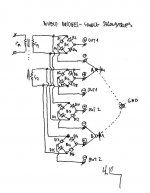
Some idea when are one pair secondaries connected to two (and more) pairs bridges.
If ground point of upper pair (point A) is connected thru star ground point together with ground point of lower pair (point B), I see some problems (maybe):
1. Some diodes are connected parallel (D1 with D9, D3 with D11, D5 with D13, D7 with D15), and if these diode pair are not matched, exist possibility (exist anyway) that current for upper amp flow thru star ground and diodes dedicated to lower amp (and vice versa). This current thru grounding wires can produce hum (IMO); isolation between amps is smaller.
2. If bridges have some diode double and some single, is not this nonlinearity-nonsimetry in rectification?
3. If we make mistake and tray to use sec1 for + rail of upper amp and for - rail of lower amp, thru ground we make short connection (antiparallel two diode). Maybe is this reason for some fuse blows.
At end, I can speculate that grounds of amps are not connected together (then this problems are away), but this is true (IMO) only when input signal is connected thru line transformer.
Regards
Attachments
JanGeorge, you did wire the two pair of bridges like this, in parallel to the secondaries, right...?
Yes . I attach the schematic, which is for one channel only. The bridges for the second channel are wired in parallel. The "grounding" is also shown on the right. The fuse on the primary is 3A fast. The 2A fast was marginal. The 1.5A fast didn't make it. Chassis is grounded. Signal ground is floating.
Regards
George
Attachments

moamps said:
At end, I can speculate that grounds of amps are not connected together (then this problems are away), but this is true (IMO) only when input signal is connected thru line transformer.
Regards
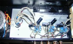
moamps, I wired exactly like on your schematics, except three channels in parallel.
Each star ground for each channel are in fact not connected ! I have two star grounds per channel. First starground for psu and speakers, and second starground for inputs. Those two star ground are then connected. But for each channel only.
I will have to investigate futher why I cannot get it to work with six bridges, cause it works fine with two bridges.

Attachments
Kuei Yang Wang said:
Later when I could get big rectifier bridges we found that scheme with a dual winding and a dual diodes with a transformer per voltage sounded notably better and that in a PA Amp!
I could take some guesses here but will refain.
Thanks a lot Kuei !!! I tried your concept
on my gainclone and it rocks!
During first listening session I noticed immediately wider soundstage and more details !
Before I used single bridge (4 fast recovery) / one transformer for two channels. So in the current setup I'm using two transformers (EI 160VA) with only two MBR20100CT 🙂 for both channels.
This is the best setup from all combinations I had before: (2 bridges schottky, 2 bridges fast recovery and 1 bridge fast recovery)
🙂))
v.
- Status
- Not open for further replies.
- Home
- Amplifiers
- Chip Amps
- 2 Rectifier bridges : Why ?